
- This Page
- OEM Wire Colors
- Antenna
- LED
- Valet Button
- Hood Pin
- Siren
- Sensor Shock
- Sensor Tilt
- Alarm Preparation
- Mount the Control Unit
- Piezo Siren
- Grounds
- Door Trigger Domelight
- Parking Lights, Trunk Trigger
- Backup Battery
- Constant 12V
- Fuse Panel Outputs
- Ignition 12V
- OEM Power Door Locks
- Aftermarket Actuators
- Testing the Alarm
- Program the Valet Button
- Troubleshooting Common Mistakes
- Home
- The Basics
- Stealth Installs
- Misc Security
- Kill Switches
- Convenience
- Modifications
- Maintenance
Stealth Car Alarm Install
1996-2000 Honda Civic
- Parts
- Alarm (Recommended: DEI Viper/Python/Clifford/Hornet, non Remote Start)
- Battery Backup Module DEI 520T
- Piezo siren DEI 513T
- One or two of the following sensors:
- Glass Breakage DEI 506T
- Tilt DEI 507M
You can get sensors and the backup module from Amazon. DEI sensors and backup modules work with all alarms.
You can expect to have your interior taken apart anywhere from 10 hours to several days. Even so, it's still in a driveable state. This install is virtually identical to any DEI (Viper/Python/Clifford) alarm into any 2 door Honda/Acura roughly between the years of 1988 and 2005.
OEM Wire Colors
| 1996-2000 Honda Civic | ||
|---|---|---|
| WIRE | COLOR | LOCATION |
| 12 VOLT CONSTANT | DASH FUSEBOX OPTION OUTPUT | |
| STARTER | BLACK/WHITE | STARTER RELAY |
| IGNITION | BLACK/YELLOW | BROWN PLUG ABOVE FUSEBOX |
| PARKING LIGHTS (+) | RED/BLACK | DRIVER'S RUNNING BOARD |
| DOOR TRIGGER (-) | LIGHT GREEN/RED | DRIVER'S RUNNING BOARD |
| TRUNK TRIGGER (-) | BLUE/BLACK | DRIVER'S RUNNING BOARD |
| FUEL PUMP (+) | YELLOW/GREEN | DRIVER'S RUNNING BOARD |
| POWER LOCK (-) | GREEN/WHITE | SIDE BLUE PLUG ON DASH FUSEBOX* |
| POWER UNLOCK (-) | GREEN/ORANGE | SIDE BLUE PLUG ON DASH FUSEBOX* |
All wires must be verified with a multimeter. *99-00 Civics have a door lock module below hood release handle. Main relay is on the passenger side beside the glovebox.
Alarm Preparation

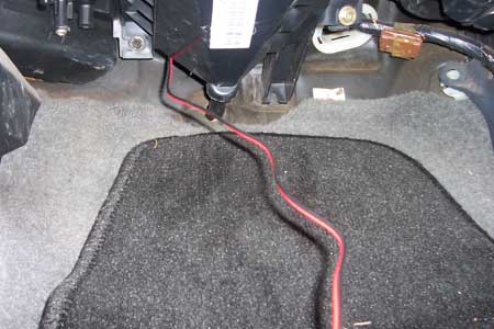
Cut the red wire 1 inch before the fuse because we will be connecting this to the backup battery's grey wire.

Cut the slack from the yellow and orange wires that go to the start-kill relay. The wires you're twisting together will have to be the same length.

If you're doing a fuel pump kill or any kind of kill that doesn't involve the ignition harness, then you only need one yellow wire on the relay.


First check the alarm manual to make sure the domelight output isn't listed in mA. If it is, you'll need a relay if you want to connect the domelight. If it's a regular negative output, you can tie it in with the door trigger wire. Cut the black/white (negative dome light output) wire at about the same point as the red wire and splice it together with the green (negative door trigger input) wire. I like to keep the alarm's cutting and splicing all at the same level because it's easier to trace down later if there's a problem. Another thing I always do is take the leftover black/white wire and branch off the black wire. Now you can use this extra ground for the siren ground wire.

De-pin the white/blue (never used), purple (positive door trigger input doesn't apply to Japanese cars), and red/white (negative aux output used for trunk poppers etc) wires.
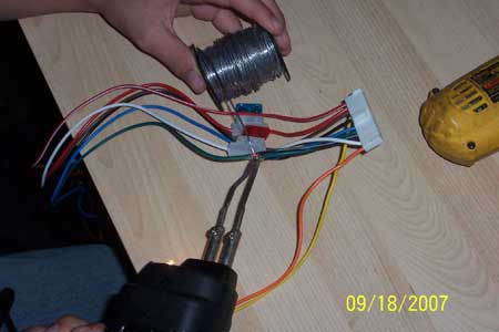
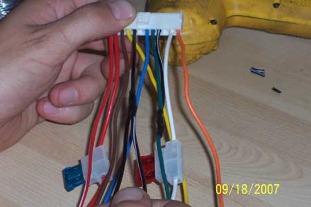
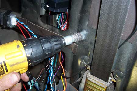
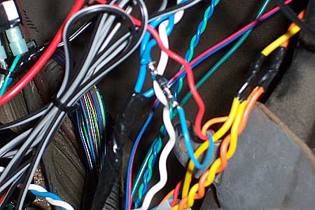
If you haven"t noticed yet, alarms have a lot of wires to manage. To help keep them clean and organized, you should twist wires together if they're going the same direction or are connecting to the same point. Put them in the end of your cordless drill, tighten the chuck down, hold the wires tight, and pull the trigger.
Alarm Peripherals
The best way to start the install is to get all of the alarm's peripherals out of the way. By peripherals I mean both sirens, the antenna, the valet button and LED, all the sensors including the hood pin, and the backup battery mount.
Antenna
For the best possible range, mount the antenna up high and tuck any excess length loosely in the headliner. Never tightly bundle up the wire or range will suffer. Another aspect of antenna range is the strength of the power and ground connections. I'll go over that later.


LED

The best mounting place for the LED is a pop out panel that is easily visible from outside the vehicle. Drill a hole using a 17/64 or 1/4 bit. The manual says 9/32, but then the LED will be loose so use the next size smaller and a round file. Press the LED in on a soft surface like a carpeted work bench.
The only bad thing about doing a stealth install is that you'll have to extend the 22 gauge LED, valet, and motion sensor wires. I keep junkyard LEDs available so I can cut off the LED and extend the wires.
Valet Button


You can mount the valet button the same as you would an LED, except you want to hide it. I usually just wait until the install is finished, program whatever options I want, and then remove the valet button. You can put the alarm into valet by hitting lock, unlock, lock quickly in sequence on the remote.
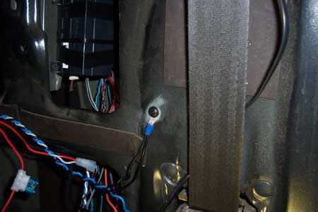
Hood Pin

You can mount a hoodpin by enlarging an existing hole or using a backstrap. Just make sure the surface that contacts the pin from above is perpendicular to it. This car already had a hoodpin. As you can see, rust is a real problem with hoodpins. You will probably have to clean or replace the pin from time to time.
Siren
Customizing Siren Tones
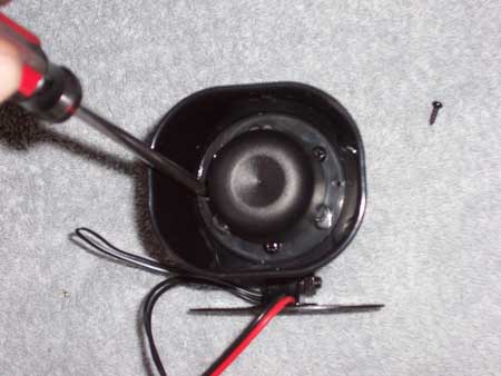
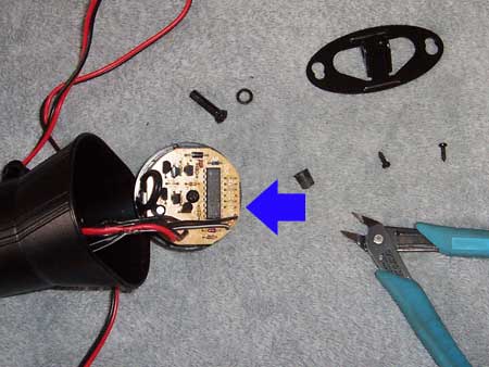
You can customize the sound of the siren by eliminating any of the six tones. Remove the two little screws surrounding the horn. Remove the 8mm, and use a pick to pop out the grommet on the wires. Tap the siren on the ground and carefully seperate it from its housing. You can preview the tones by connecting the siren wires to your drill's battery or the car battery. Inside, you'll see a row of six loops. Clip a loop to eliminate a tone. I get rid of the most annoying of the tones: J4 and J6.
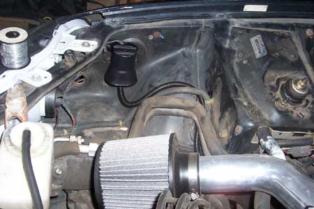
Install the siren in the engine bay using metal tapping screws. Cover the siren wires with split loom and run them through the firewall at a factory grommet, or drill a hole and install your own grommet. Later you will run these wires all the way back to the alarm.
Engine Bay Siren
Hidden Piezo Siren
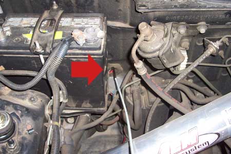
Tap into the brown and black/white wires that will be running to the siren under the hood. Put an inline fuse on between the brown wire and the engine bay siren's red wire. That way the thief can't short out your interior siren by cutting your engine bay siren's power wire and grounding it. Use a 1A fuse.


There wasn't a whole lot I could do with the engine bay siren on this car, so I decided to make up the difference on the piezo siren. I fabricated a mount using a backstrap and some speed clips.

The blue and green wires are extended from the piezo siren. You can tie the ground in with the alarm grounds as I did here, or simply ground it to the chassis near the siren.
The piezo's red power wire should be connected directly to the alarm's brown siren output. The engine bay siren has to be fused seperately however. I didn't have an inline fuse holder handy, so I made one using some quick disconnects. Use a small fuse, 1-4 amps is fine. If the thief cuts the engine bay siren wire and grounds it, the fuse will blow and the interior siren will be safe.

Sensor (external shock)
If your alarm came with an external shock sensor, and you bought two other sensors like I told you, don't use the shock sensor. It's basically worthless.
Sensor (tilt)
Use a metal tapping screw to mount the tilt sensor parallel to the ground. The red and orange wires can be tapped into the alarm's red and orange. The tilt sensor's blue negative trigger wire can be tapped into the alarm's blue wire but if you have it connected to the trunk trigger, you should diode-isolate it. You could also tap it into one of the other sensor's blue wire.
Getting Serious
On the 96-00 Civic, it's much easier to just pull the driver's seat. Unplug the connector, pop out the tab, and then remove the four 12mm bolts holding in the seat so you can pull it out.
Pull the cover upward and remove the 14mm bolt.
Remove the rear seats while you're at it. The lower cusion is held in by a bolt. Flip the seats down and get a wrench in there. Then pull from the back side of the lower cushion forward and unhook it at the base of the seat. Remove the seat backs.
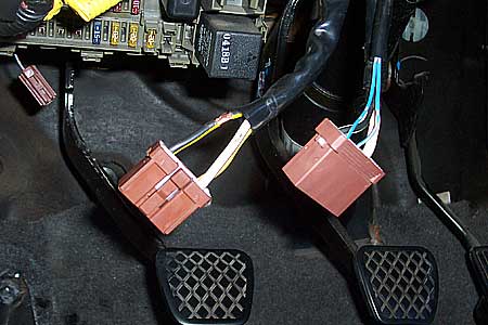
Remove the lower dash panel and the kick panel that surrounds the hood release handle. Then remove the plastic running board.

Remove the screws and pop tabs so you can pry out the driver's side rear quarter panel plastic. This is where we'll be hiding the alarm.
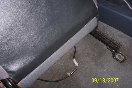
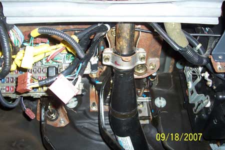
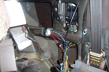
Mount the Control Unit
I strapped the backup battery to the control unit using electric tape, double sided tape, and some zip ties. Then brain was mounted to the sheet metal using metal tapping screws.
Backup Battery (DEI 520T)


Leave the module unplugged until the wiring is completed. Tap the blue trigger wire into the blue trunk trigger wire or the grey 22 gauge hood pin input on alarm's that have it. It's a good idea to isolate the triggers using a diode. The high end alarms come with the diodes in this white heat shrink.
The diagram that comes with the DEI 520T is better than any instructions I could ever give. Some people get tripped up on the power connection. Cut the alarm's red power wire an inch before the fuse and connect it to the backup module's grey wire. Then connect the module's red wire to constant 12v coming from the car.
Wiring
Even though I'm telling you the locations, you have to verify the wire using a multimeter. The "Basics" section linked at the top of this page has instructions on how to verify wires.
Grounds
Door Trigger/Domelight
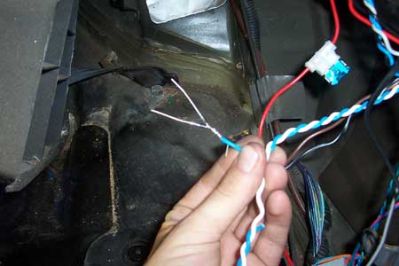
96-98 Civics w/keyless entry have it built into the factory stereo. If you have an aftermarket stereo, there is a chance that your domelight doesn't turn on when the doors open. Set the dome light to the "door" position and test it. If it doesn't come on, you'll have to pull out your stereo and find the green plug. Cut the light green/red and light green/black wires and connect them.
The door trigger wire is in the wire bundle that's tucked up in the rear interior crossmember. It's a thick light green/red. The fuel pump wire is also found in this bundle. It's yellow/green.
Close all the doors, set your meter to continuity, connect one probe to chassis ground and the other to the suspected wire. There should be no continuity (meter shows 1). Open a door and the meter should drop to 0. Test each door individually.
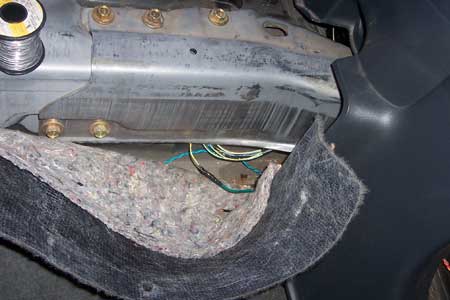
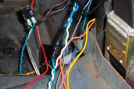
Parking Lights, Trunk Trigger

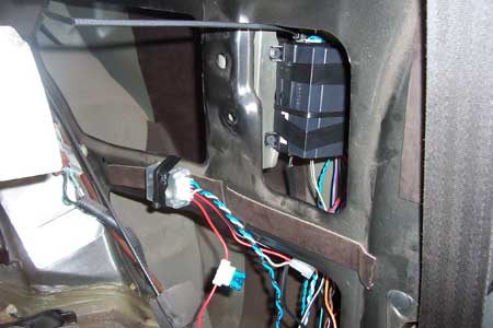
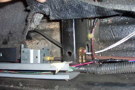
The red/black parking light wire and blue/black trunk trigger wire are found in the harness shown.
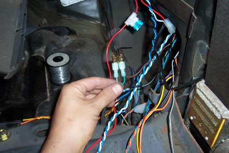
Trigger Wires
In order to keep the circuits seperated, you will have to isolate certain trigger wires. That way you don't have the trunk warning light coming on when the sensor is triggering. You can use 1-5 amp diodes.

The striped ends of the diodes go to the negative side, and the other ends are tied together and then soldered to the alarm's blue negative trigger wire.
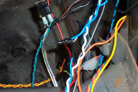
Each trigger wire, ie battery backup, trunk, sensor, is then connected to the individual diodes and taped up.
I forgot one of the triggers so I tied it in later.
Then I taped over the whole thing against the wire for strength.
Constant 12V

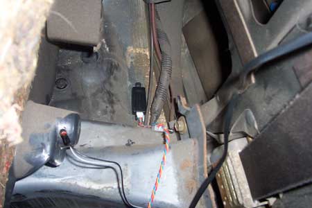
Tap into the far left option output on the under-dash fuse panel for constant 12v. You can use a female quick disconnect, but I like to use these brown 1 pin connectors that I scavenge from the junkyard. You can find under the door panels and in the engine bays of 92-95 Civic's and 94+ Integras. You also need an inline fuse holder. I just re-use the alarm's red wire that I chopped off for the battery backup module.
Ignition 12V
I always unplug the ignition harness and re-route it over the top of the steering column. If the thief goes for the ignition harness, this may slow them down a bit. Then tap into the black/yellow wire for the alarm's yellow ignition input. Your start-kill relay's yellow wires will need to connect to this wire as well.
Running Wire
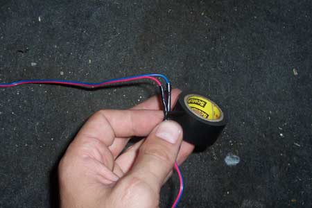
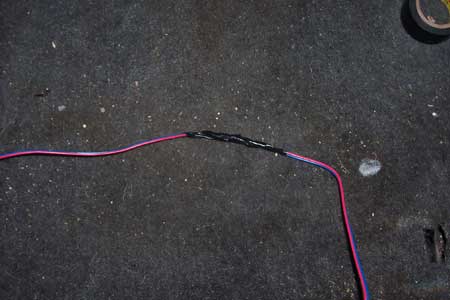
Constant 12v, Ignition 12v, door locks, siren and LED wires will all need to be ran up front. Many of these wires will need to be extended. If you want this to be as clean/quick/easy as possible, you'll prepare the extension wire beforehand. Get ahold of some 18 gauge blue, green, yellow, and red wire. Twist them all together. Get some 18 gauge speaker wire for the siren and LED. Bundle the wires together and tape the ends to keep them together.

Cut the tape with a razor and pry open the plastic cases. This is where you'll be running all the wires through to the front.

Loom the wires to keep them from chaffing on this edge. You may want to loom them all the way to the plastic case, and then from the plastic case to the fuse box.
Door Locks
OEM Power Door Locks
If your car has power door locks, you will want to hook up the keyless entry. If your car has manual locks you can install aftermarket actuators (recommend 2 wire).
3 Pin Door Lock Output
There are several variations of door lock outputs on DEI alarms. One is a 3 pin output with reversing polarity outputs on the outer pins and 12v constant on the middle pin. The alarm comes with a small plug connector that only has the blue and green outer wires and an empty pin in the center. On Japanese cars with OEM power door locks, you simply connect the green - lock output to your car's lock wire, and the blue - unlock output to your car's unlock wire.
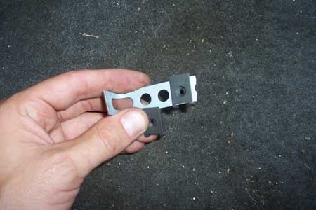
Sometimes these alarms come with a DEI 451M, which is a double relay pack with a ribbon harness that plugs into the 3 pin plug in place of the 2 wire doorlock harness. This relay pack is needed for American cars that have the 5 wire door lock system, or for adding aftermarket actuators. Though you wont need the 451M if your car has power door locks, don't discard it!! It's very useful for other things.
Onboard Door Lock Relays
The other variation is basically a built-in 451M, sometimes with an extra wire or two for the built-in "Flex" domelight relay. The door lock wires are the same colors as found on the 451M and would be wired the same on cars that need them. But with OEM door locks, most of them are de-pinned. The domelight flex input (87) is grounded, typically tied in with the main harness ground along with any other ground wires. These wires have nothing to do with the door locks.
- Violet - Ground
- Blue/Black - Unlock wire
- Brown/Black - Not Used
- Violet/Black - Ground
- Green/Black - Lock wire
- White/Black - Not Used
- White/Violet - Flex Relay 87 - Ground
- White/Brown - Flex Relay 87A - Not Used
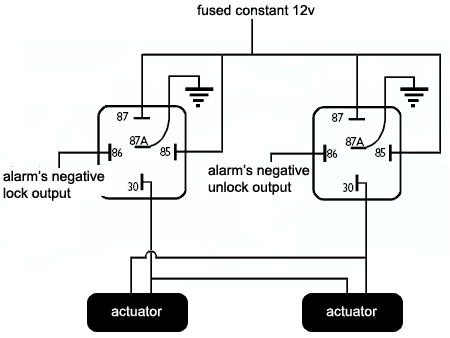
Aftermarket Actuators
Some DEI alarms have onboard door lock relays with six door lock output pins instead of three. This is how you wire them to aftermarket actuators.
- Violet - Constant 12v
- Blue/Black - Unlock wire on actuator
- Brown/Black - Ground
- Violet/Black - Constant 12v
- Green/Black - Lock wire on actuator
- White/Black - Ground
- White/Violet - Flex Relay 87 - Ground
- White/Brown - Flex Relay 87A - Not Used
Using Two Relays Instead of the 451M
Testing the Alarm
Close the doors and trunk and arm the alarm. Make sure both doors lock when armed, unlock when disarmed. Also make sure the parking lights and LED flash. Make sure both sirens chirp. Unlock the door with the key and make sure it triggers the alarm, then test the other door and the trunk. Make sure the car wont start when the alarm is going off, but will start when it's disarmed. Try putting the alarm in valet mode and taking it out (turn the key on but the engine off and tap the valet button).
Program the Valet Button
By default it takes one press on the valet with the ignition on to put the alarm in valet. Program it for 2 or more presses and write it down in the booklet, or just program whatever options you want and then remove the valet button altogether.
Once you are satisfied that the alarm is fully functional, put your interior back together and give it one more quick test.
Troubleshooting Common Mistakes
- Problem: Alarm doesn't respond to remote.
- Solution: Check the alarm's power and ground, power fuse, and that the antenna is plugged in all the way. DEI's paging alarms that don't have remote start have the ability to program a single remote to control four cars. Look for the little number icon. It can be anything from 1-4 but should be set to 1. You can change it by pressing the little blue button on the back of the remote.
- If it's a used alarm, you may need to reprogram the remote to the alarm using the key and the valet button (refer to the manual).
- Problem: Only the driver's door triggers the alarm.
- Solution: You tapped into the driver's side door trigger. The other doors are upstream of this wire. Tap into the passenger-side door trigger instead.
- Problem: Alarm doesn't trigger the door locks.
- Solution: Both the lock and unlock wire must be connected for the door lock system to work.
- Problem: Doors lock on disarm, unlock on arm.
- Solution: You have the lock/unlock output wires reversed.
- Problem: Alarm worked initially, but now it doesn't go off.
- Solution: Cycle the ignition. DEI alarm's have nuisance protection, so if you keep triggering a zone, eventually it will ignore that zone until you have cycled the ignition (turn the key on and off).