- This Page
- OEM Wire Colors
- Antenna
- LED
- Valet Button
- Hood Pin
- Siren
- Sensor Shock
- Sensor Motion Proximity
- Sensor Glass Breakage
- Alarm Preparation
- Remove Rear Seats
- Remove Rear Quarter Plastic
- Mount the Control Unit
- Piezo Siren
- Grounds
- Door Trigger Domelight
- Parking Lights, Trunk Trigger, Fuel Pump
- Start-kill
- Backup Battery
- Constant 12V
- Ignition 12V
- Power Door Locks
- Aftermarket Actuators
- Testing the Alarm
- Program the Valet Button
- Glossary
- FAQ
- DEI Harness Preparation
- Home
- The Basics
- Stealth Installs
- Misc Security
- Kill Switches
- Convenience
- Modifications
- Maintenance
Stealth Car Alarm Install
1990-1993 Acura Integra
The standard type of alarm install you get when you pay a professional to install your alarm just isn't effective. In order for an alarm to be effective, the control unit must be invisible and undetectable, the siren must be hidden and inaccessible, all wiring should be concealed in split loom, the alarm should have its own backup battery, and the alarm must be able to detect all types of intrusion. To accomplish this, you'll need the following:
- Parts
- Alarm (not remote-start) (Recommended: DEI Viper/Python/Clifford/Hornet)
- Battery Backup Module (not siren) DEI 520T
- Piezo siren
- One or two of the following sensors:
- Glass Breakage DEI 506T
- Tilt DEI 507M
OEM Wire Colors
| 1990-93 Acura Integra | ||
|---|---|---|
| WIRE | COLOR | LOCATION |
| 12 VOLT CONSTANT | A OR C | FUSE BOX OPTION OUTPUT |
| STARTER | BLK/WH | FUSE BOX |
| IGNITION | BLK/YEL | FUSE BOX |
| PARKING LIGHTS (+) | RED/BLK | DRIVER'S REAR QUARTER |
| DOOR TRIGGER (-) | GRN/RED | DRIVER'S RUNNING BOARD |
| TRUNK TRIGGER (-) | GRN/BLK | DRIVER'S REAR QUARTER |
| FUEL PUMP (+) | YEL/BLK | DRIVER'S RUNNING BOARD |
| POWER LOCK (-) | GRN/WH | DRIVER'S KICK |
| POWER UNLOCK (-) | GRN/RED | DRIVER'S KICK |
*You must put a fuse in #13 to use C as a Constant 12v output. ALL WIRES MUST BE VERIFIED WITH A MULTIMETER.
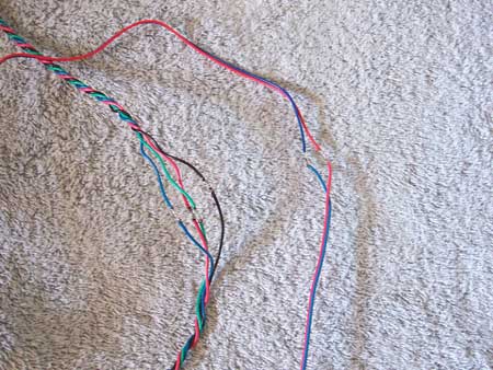
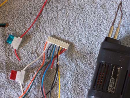
Break It Out
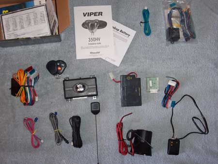
The bottom row is all the alarm peripherals that will be installed first. In the top right is the 451M that comes with some DEI alarms. You will only use it if you have aftermarket actuators, but you wont use the resistors. If you have OEM power door locks, you'll use the small harness with the blue and green wires. Bottom right is the Crime Guard AU94T motion/proximity sensor with a DEI shock sensor harness plugged into it. Between that and the 451M is the 520T battery backup module.
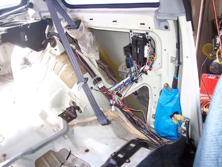
Alarm Peripherals
The best way to start the install is to get all of the alarm's peripherals out of the way. By peripherals I mean both sirens, the antenna, the valet button and LED, all the sensors including the hood pin, and the backup battery mount.
Antenna
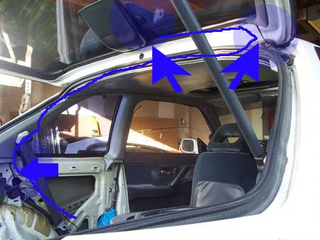
Range is critical for two-way paging alarms. For the best possible range, mount the antenna up high and tuck any excess length loosely in the headliner. In this example I mounted the antenna on the rear hatch glass next to the third brake light and zig zagged the slack down to the alarm. Never tightly bundle up the wire or range will suffer. Another aspect of antenna range is the strength of the power and ground connections. I'll go over that later.
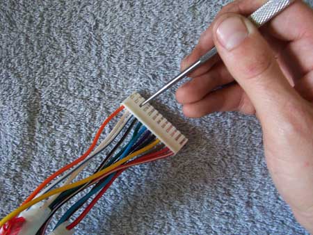
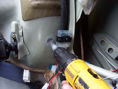
LED
The best mounting place for the LED is a pop out panel that is easily visible from outside the vehicle. Drill a hole using a 17/64 or 1/4 bit. The manual says 9/32, but then the LED will be loose so use the next size smaller and a round file. Press the LED in on a soft surface like a carpeted work bench.
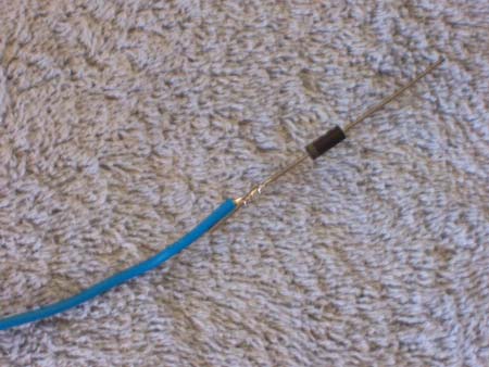
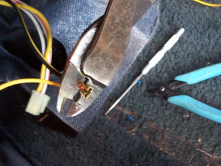
The only bad thing about doing a stealth install is that you'll have to extend the 22 gauge LED, valet, and motion sensor wires. I keep junkyard LEDs available so I can cut off the LED and extend the wires.
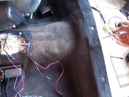
The grappling tool is a good example of how having the right tool at the right time is a lifesaver. Use it to run wires under the carpet between the ebrake and the rear seat.
Valet Button
You can mount the valet button the same as you would an LED, except you want to hide it. I usually just wait until the install is finished, program whatever options I want, and then remove the valet button. You can put the alarm into valet by hitting lock, unlock, lock quickly in sequence on the remote.
Hood Pin
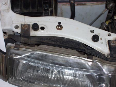
The low end alarm I'm using didn't come with a hood pin, but you can buy one from Best Buy or Circuit City. Just get it mounted for now and run a grey (preferably) wire through the firewall on the driver's side.
Siren
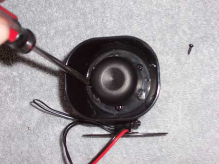
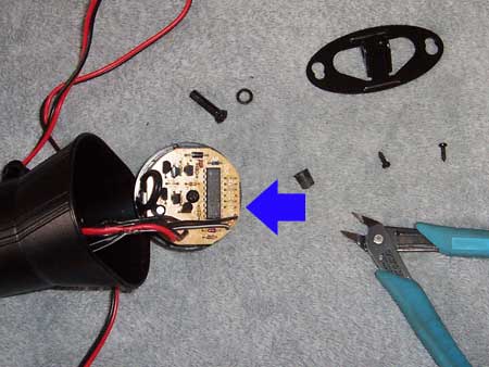
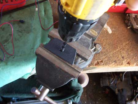
You can customize the sound of the siren by eliminating any of the six tones. Remove the two little screws surrounding the horn. Remove the 8mm, and use a pick to pop out the grommet on the wires. Tap the siren on the ground and carefully seperate it from its housing. You can preview the tones by connecting the siren wires to your drill's battery or the car battery. Inside, you'll see a row of six loops. Clip a loop to eliminate a tone. I get rid of the most annoying of the tones: J4 and J6.
Install the siren in the engine bay using metal tapping screws. Cover the siren wires with split loom and run them through the firewall at a factory grommet, or drill a hole and install your own grommet. Later you will run these wires all the way back to the alarm.
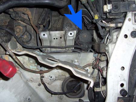
On the DA and many other cars, a great place to mount the engine bay siren is beneath the battery tray. Wrap the wires in some small diameter split loom and zip tie it alongside the factory wiring.
Sensor (external shock)
If your alarm came with an external shock sensor, and you bought two other sensors like I recommend, don't use the shock sensor. It's basically worthless.
Sensor (motion/proximity)
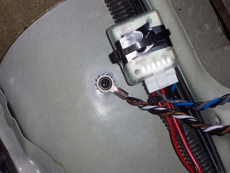
Mounting
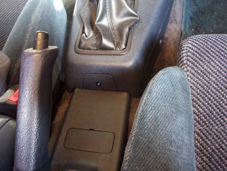
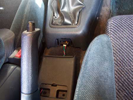
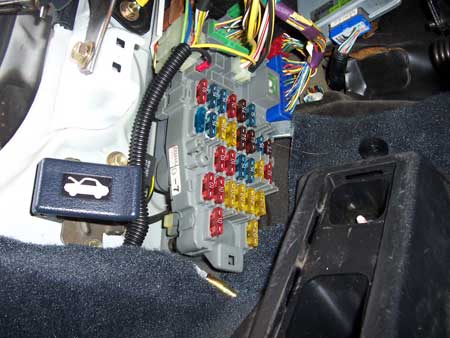
Mount the motion sensor low and in the center of the interior. don't encase it in sheet metal. Ideally, it should be easily accessible because it will take a lot of trial and error to get the sensitivity adjustment right. If it wont be accessible, leave the center console partly disassembled. In this example, I mounted it behind this removable plate using velcro.
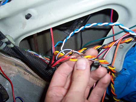
Wiring
You'll need a plug from a DEI sensor harness to plug the AU94T into a DEI alarm. The DEI glass breakage sensor has a Y harness. Otherwise you'll have to find a shock sensor in the junkyard from a recent model alarm. The sensor harness wont reach from the center console to the alarm, so you'll have to extend it. Some very small diameter heat shrink will make this not suck so hard. You can cut off the alarm-side plug from the harness that comes with the Crime Guard sensor and use it to extend the wires. Otherwise you'll need some 22 gauge wire, preferably in four different colors.
The AU94T has the same four wire colors with the same four functions as a DEI shock sensor, but if you look closely you'll realize that the AU94T pin positions for the green and blue wires are switched. If you plug in a DEI sensor harness, you'll have the warn and full trigger pins reversed and the sensor wont work properly. Make sure to de-pin the blue and green wires on the sensor side and switch them. On the other hand, if you're extending the wires, naturally you'll match up the colors and the problem solves itself.
If your alarm doesn't have an available sensor port, throw away your shock sensor and use the motion sensor in its place. Shock sensors are utterly useless. If your alarm has an internal shock sensor and no sensor ports (wow, bad choice in alarms) you will have to splice the motion sensor in according to the following table.
| Motion Sensor | Alarm |
|---|---|
| Red | Red (constant 12v)* |
| Black | Orange (ground when armed) |
| Green | Green (negative door trigger input) |
| Blue | Blue (trunk trigger input) or Light Gray (hood pin input) |
*In the case of a backup battery, connect between the backup battery and the car, not between the backup battery and the alarm.
Adjusting the Sensitivity
Dialing in the sensitivity of this sensor is tricky but very rewarding. Using this sensor on a DEI alarm makes it extremely sensitive. Your final settings will be within the first few degrees of the sensitivity knob's lowest setting. But once you get the sensor dialed in, it will seem like your alarm is intelligent. Unfortunately the sensor will only respond if someone approaches the doors or wheels, or if they reach inside the window. By installing a second sensor, I was able to get good rear coverage, but I have never been able to cover the engine bay because the dash and firewall block the signal from the sensor.
Start by turning both knobs completely counterclockwise (less sensitive), then turn the warn knob about 1/5th clockwise. Roll down one of windows so you can reach in and make quick adjustments. Now step back about 5 feet, arm the alarm and wait about 15 seconds. When you first arm the alarm, it ignores the sensors for a short period of time. Now rapidly approach the door of the vehicle. If it fully triggers the alarm, back off the sensitivity and try again. If it completely ignores you, jump around a little bit. If it still ignores you, increase the sensitivity just a hair. Seriously, the difference between a non-responsive motion sensor and one that sounds the false alarm almost immediately is just a hair when you're using the strange combination of this Crime Guard sensor and a DEI alarm. Now you will do the same thing with the hard trigger knob except that you will be reaching in an open window and you want the alarm to trigger immediately. (There is a green and a red LED on the sensor to indicate warn and hard trigger respectively.)
Sensor (tilt)
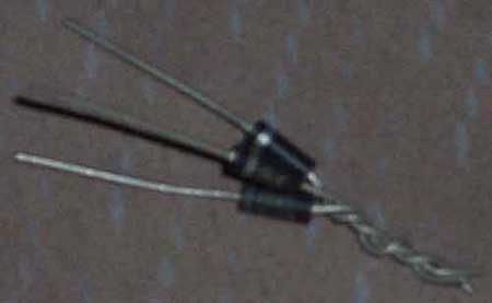
The tilt sensor mounts with a single screw. The mounting location isn't critical, as long as it's parallel to the floorboard. Put a diode on the end of the trigger wire with the striped side facing the sensor. You'll need a diode on the other trigger that you're isolating, with the non-striped ends tied together and connected to the alarm side. Connect the tilt sensor's orange wire to the orange negative ground when-armed output on the alarm. Connect the red to constant 12v before the backup battery.
Sensor (glass breakage)
I usually mount the glass sensor module alongside the alarm control unit. Run the mic so that it's exposed to the open air of the cabin. Placement and orientation doesn't affect its performance as long as it's not sealed off in a seperate air space from the windows. The harness is plug and play.
Alarm Preparation
De-pin the white/blue (never used), purple (positive door trigger input doesn't apply to Japanese cars), and red/white (negative aux output used for trunk poppers etc) wires.
Cut the red wire 1 inch before the fuse because we will be connecting this to the backup battery's grey wire. Cut the black/white (negative dome light output) wire at about the same point as the red wire and tie it together with the green (negative door trigger input) wire. I like to keep the alarm's cutting and splicing all at the same level because it's easier to trace down later if there's a problem. Another thing I always do is take the leftover black/white wire and branch off the black wire. Now you can use this extra ground for the siren ground wire. Cut the yellow and orange wires that go to the start-kill relay. I like to make them the same length as the relay's green and black wires.
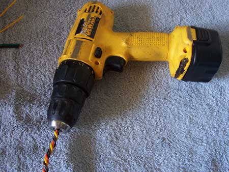
If you haven"t noticed yet, alarms have a lot of wires to manage. To help keep them clean and organized, you should twist wires together if they're going the same direction or are connecting to the same point. Put them in the end of your cordless drill, tighten the chuck down, hold the wires tight, and pull the trigger. You can twist the blue (trunk trigger input) with the white wire (parking light output). Twist the brown, black/white, orange, and yellow wires together. Twist the backup module's grey, blue, and black wires since they will all be tapping into the alarm wires. Twist the start-kill relay's green, black, and yellow wires together in one bundle, and the relay's other yellow and orange wires in another bundle.
Getting Serious
Remove Rear Seats
Now it's time to start taking apart your interior. The lower seat cushion is held in by one or two 10mm bolts in the center between the lower and upper seat cushion. Pull it up from the back and slide it out of the hooks in the front. Disconnect the rear seat backs at the outside edges first. On the DA, you have to remove the rear passenger side seat back first so you can get to the 10mm in the middle.
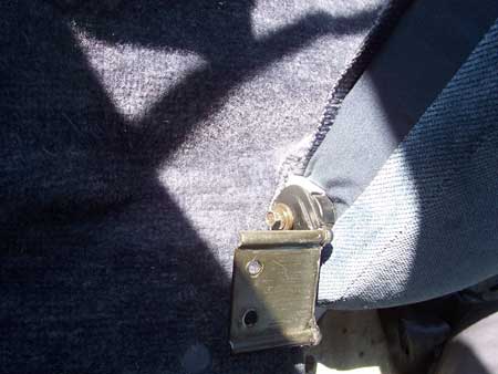
Remove Rear Quarter Plastic
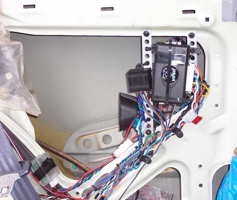
Track down and remove all the screws and work the rear quarter plastic out from behind the seatbelt. I forgot to take a picture until after I had the control unit mounted and most of the wiring finished. Just pretend like you don't see it. You'll ruin the surprise.
Mount the Control Unit
Tape and then zip tie the backup battery to the back of the control unit, and then secure it using backstraps, metal tapping screws, and zip ties. SURPRISE!
Wiring
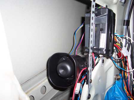
Piezo Siren
Find some place to mount the piezo next to the alarm brain. Point it downwards if you can so that moisture wont pool up inside. I'm using the siren that came with the alarm because this car already had a siren mounted in a good spot in the engine bay.
Tap into the brown and black/white wires that will be running to the siren under the hood. Put an inline fuse on between the brown wire and the engine bay siren's red wire. That way the thief can't short out your interior siren by cutting your engine bay siren's power wire and grounding it. Use a 1A fuse.
Grounds
Group all the grounds together and crimp them all into one 8 gauge ring terminal. Choose a mounting point that is one continuous piece of sheet metal with the frame rails. Scrape the area down to the bare metal using a wire wheel, then mount the ring terminals using a star washer and a short metal tapping screw.
Door Trigger/Domelight
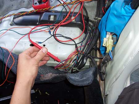
The door trigger wire runs along the base of the rear seat beneath the carpet. On Hondas/Acuras up to 00, you always want to tap into the passenger-side door trigger wire. Connect the alarm's green (negative door trigger input) to the light green/red (wire color varies with some cars). Honda/Acura door trigger wires have real thick insulation on them. Close all the doors, set your meter to continuity, connect one probe to chassis ground and the other to the suspected wire. There should be no continuity (meter shows 1). Open a door and the meter should drop to 0. Test each door individually.
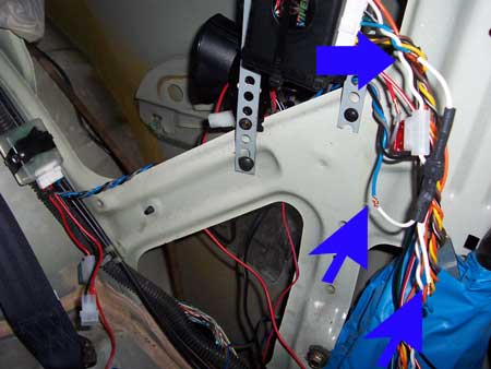
Parking Lights, Trunk Trigger, Fuel Pump
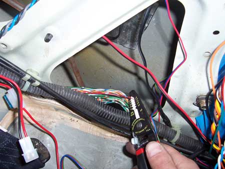
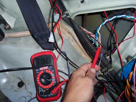
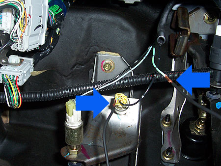
All of these wires can be found in the bundle going down the driver's side of the car to the rear. The parking light wire is always red/black. If you're putting a start-kill on the fuel pump, you can look up the wire color on the Fuel Kill page. I already have a fuel kill switch obviously, so I'm doing the Engine Bay Ignition Kill. The trunk trigger and door trigger (usually light green/red) wire colors vary so you will have to look it up in the links provided. On the DA, the trunk trigger is an 18 gauge green/black. Unfortunately there are two 18 gauge green/black wires in the same bundle, so you'll have to check each of them with a multimeter. Set your meter to continuity. Ground the black probe and connect the red probe to the suspected wire. Pop the trunk. The correct wire will show continuity to ground when open, and infinite resistance with it shut.
The alarm I'm installing has a trunk trigger input but no hood trigger input. I also have the battery backup trigger to contend with. The best thing to do is to tie them all into the alarm's blue negative trunk trigger input. You'll want them isolated because you don't want to have the trunk light on when the hood is open. Diodes have a stripe on the negative side. Twist the positive sides together and solder them to the alarm-side of the blue trunk trigger input. Then solder each trigger to its own diode on the striped ends. Make sure to tape over the entire diode when you're done. If you have an LCD two-way paging alarm, tie the backup battery and hood pin into the grey 22 gauge negative hood trigger input. There's no need to diode isolate them. If the battery is disconnected, the remote will tell you that your hood is open.
start-kill
Choose between the three start-kills from the other pages on this site. I've provided diagrams for either a manual switch or remote control via the alarm.
Low end DEI alarms come with an external relay. Cut the oem starter wire (black/white 10 gauge). Connect the relay's black 87 to the starter side of the starter wire. Connect the relay's green 30 to the key side. Connect the yellow wire to the car's black/yellow ignition wire. You can substitute any other start-kill circuit in place of the starter, ie clutch, neutral safety, fuel pump, or even the ignition.
High end DEI alarms give you three heavy gauge green/stripe wires. First, choose either normally open or normally closed. Normally open is more secure but if the alarm fails, you'll be stranded. Cut the start wire and connect the green/white wire to one end and the green wire to the other end. Cap off the green/black. You'll need to program the alarm option for normally open which is menu 2, option 11. If you want to do normally closed you'll use the green/white and green/black wires, then cap off the green wire. You wont have to change the programming.
Remote start alarms have a relay pack with 10 gauge green and purple wires for the start-kill/remote start. Remote start alarms don't usually apply to stealth installs unless you're putting the alarm brain behind the cluster. Cut the black/white starter wire and connect purple to the starter side and green to the key side.
High end DEI alarms and Remote start alarms allow you to use the orange ground-when-armed wire for a second start-kill, but you'll have to supply your own relay. Use a diagram from one of the three kill switch pages from this site. If you do a fuel pump kill, I strongly recommend a second start-kill on the starter, clutch, or neutral safety wire because otherwise it may be easy for a thief to diagnose when your car starts and then immediately stalls.
Clutch Kill
In this case, I already had a manual fuel kill switch installed. Unfortunately fuel kill switches alone are not difficult to diagnose. The engine cranks, but will not start. That's either fuel or ignition. All manual transmission cars have a built in clutch kill switch that requires you to push the pedal down to start the car. The idea behind an alarm-controlled clutch kill switch is that when the alarm is armed, it fools the car into thinking the clutch is not pushed in. The engine doesn't crank, and the thief suspects a starter kill. Thieves are very accustomed to starter kills on the ignition harness. They don't see clutch kills that often.
Automatic transmission vehicles have a similar setup that prevents the car from starting unless it's in park or neutral. You can do the exact same type of kill on the neutral safety wire found near the shifter. Check the repair manual wiring diagram for location and color.
Many Hondas have two switches on the clutch pedal (pic is of an EM). One is used to kill the cruise control, and the other prevents the engine from starting unless the clutch is in. This is the one we want. It's usually located on top, and can be verified by making sure the car wont start when it is unplugged. There are two wires going into the switch. One is always black signifying ground. We want the other one. Cut the wire in two.
The relay is wired the same as any other start-kill. Extend each side of the cut wire and connect one end to 87a on a SPST relay, the other to 30. Connect the alarm's ground-when-armed output to 86, and connect 85 to a true Ignition 12v (branch of the alarm's yellow ignition input wire).
Backup Battery (DEI 520T)
Leave the module unplugged until the wiring is completed. Tap the blue trigger wire into the blue trunk trigger wire or the grey 22 gauge hood pin input on alarm's that have it. It's a good idea to isolate the triggers using a diode. The high end alarms come with the diodes in this white heat shrink. This alarm didn't, so good thing I have lots of them lying around.
The diagram that comes with the DEI 520T is better than any instructions I could ever give. Some people get tripped up on the power connection. Cut the alarm's red power wire an inch before the fuse and connect it to the backup module's grey wire. Then connect the module's red wire to constant 12v coming from the car.
Constant 12V
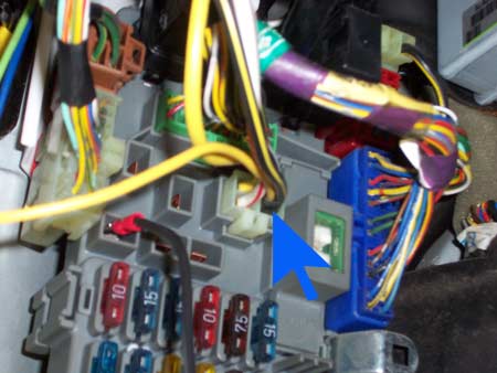
Some Hondas/Acuras; including the DA, DC, EG, and EK, have constant 12V outputs at the fuse box beneath the dash. For all others, you'll have to go to the white wire at the ignition harness or fuse box.
A provides a constant 12v, but we"re going to use C because it has a constant 12v that is independent of any other circuit and uses its own fuse in #13. B can be connected to your white positive parking light output, but we already connected it to the red/black wire in the rear of the car. D is accessory and E is ignition 2, which you might use if you install remote start. The black circle with a yellow dot inside is where you can find the black/yellow ignition wire.
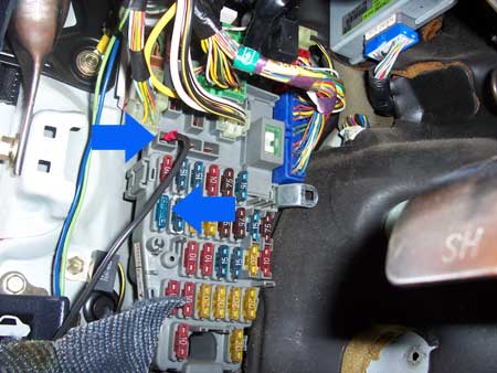
Crimp a female quick disconnect to your backup battery's extended constant 12v input wire and connect it to fusebox output C. Some heat shrink over the female quick disconnect will make it look oem. Pull the 15A fuse out of the fuseholder on the red power wire we cut off the alarm harness earlier and use it in the empty #13 slot.
Ignition 12V
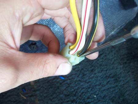
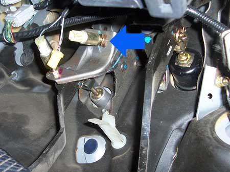
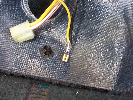
Use a straight pick to de-pin the black/yellow ignition wire.
Use the pick to pry open the little crimps over the insulation. Then strip the insulation back just slightly and lay your alarm's extended ignition input wire against the OEM ignition wire. Crimp the little tabs down.
First get your soldering iron nice and hot, then tin it and hold it against the factory quick disconnect. Feed the solder to the wire until you see it soak down between the strands of both wires.
This is what the ignition tap looks like when finished; very stealth. A little heat shrink is the icing on the cake.
Tuck all your wiring into some split loom to blend into the factory wiring.
Door Locks
Power Door Locks
This diagram is for the 90-93 Integra.
If your car has power door locks, you will want to hook up the keyless entry. If your car has manual locks, you can install aftermarket actuators (recommend 2 wire), convert to power door locks, or just not have keyless entry at all. The lock wire colors vary a lot between the years and models. On the DA, lock is green/white, unlock is green/red, and they can be found under the kickpanel. Some DEI alarms come with your choice of a 3 pin connector or the 6 wire 451M relay pack. You don't use the relay pack when you have factory door locks. Plug in the 3 pin connector and connect the green negative lock output (positive unlock) to the lock wire and the blue negative unlock output (positive lock) to the unlock wire.
Some DEI alarms come with the 451M built into the alarm brain and a 7 pin harness for the door locks. In that case, wire it up as follows (de-pin the wires marked in red):
- H3/A - Black/White to Ground (domelight)
- H3/B - White/Black
- H3/C - Green/Black to Lock wire
- H3/D - Violet/Black to Ground
- H3/E - Brown/Black
- H3/F - Blue/Black to Unlock wire
- H3/G - Violet to Ground
Aftermarket Actuators
This is an LS with manual locks but there are already actuators installed. Actuators are wired up as follows:
- H3/A - Black/White to Ground (domelight)
- H3/B - White/Black to Ground
- H3/C - Green/Black to Lock wire
- H3/D - Violet/Black to Constant 12v
- H3/E - Brown/Black to Ground
- H3/F - Blue/Black to Unlock wire
- H3/G - Violet to Constant 12v
Using Two Relays Instead of the 451M
Testing the Alarm
Close the doors and trunk and arm the alarm. Make sure both doors lock when armed, unlock when disarmed. Also make sure the parking lights and LED flash. Make sure both sirens chirp. Unlock the door with the key and make sure it triggers the alarm, then test the other door and the trunk. Make sure the car wont start when the alarm is going off, but will start when it's disarmed. Try putting the alarm in valet mode and taking it out (turn the key on but the engine off and tap the valet button).
Program the Valet Button
By default it takes one press on the valet with the ignition on to put the alarm in valet. Program it for 2 or more presses and write it down in the booklet, or just program whatever options you want and then remove the valet button altogether.
Once you are satisfied that the alarm is fully functional, put your interior back together and give it one more quick test.
Glossary
- EF: 4th Generation Civic 88-91
- EG: 5th Generation Civic 92-95
- EK: 6th Generation Civic 96-00
- EM: 7th Generation Civic 01-05
- DA: 2nd Generation Integra 90-93
- DC: 3rd Generation Integra 94-01
- Tag, Tap, Tie, Hook up: slang for Wire Together
- Hit it with: use ______ on
- OEM, OE, factory: Original equipment
- (Wire) color/color: 1st is the solid, 2nd is the stripe
- start-kill: Interrupting any circuit to prevent the car from starting or running.
- DEI: Directed Electronics, manufacturers of Viper, Python, Clifford, Hornet etc
- JDM: Who cares?
FAQ
- Q. "What's the difference between "door trigger" and "door lock"?"
- A. The door trigger is a pin switch near the door latch that triggers the domelight and an indicator on the cluster. It's in no way related to the power door locks.
- Q. "What alarm should I buy?"
- A. What alarm you should buy
- Q. "Why shouldn't I use a DEI alarm (or any alarm not intended for a standard transmission) on a standard transmission?"
- A. Remote start + manual transmission
- Q. What do you mean by "A Pillar?"
- A.
DEI Harness Preparation
Most non-remote start DEI alarm wiring harnesses are the same or very similar to the layout below. This is a quick breakdown of how each wire will be used and which will be de-pinned.
You can de-pin the following marked in red.
- H1/1 - Red/White (optional trunk pop)
- H1/2 - Red to Constant 12v
- H1/3 - Brown to Siren Red
- H1/4 - Yellow to Ignition 12v
- H1/5 - Black to Chassis Ground
- H1/6 - Violet
- H1/7 - Blue to Trunk Trigger
- H1/8 - Green to Door Trigger
- H1/9 - Black/White (join to H1/7 Green)
- H1/10 - White/Blue (never used)
- H1/11 - White to Parking Lights
- H1/12 - Orange to start-kill Relay
- H2/1 - Light Blue - Second Unlock (driver's Priority)
- H2/2 - Grey - Hood Pin Switch
- H2/3 - Orange/Black - Retained Accessory
- H2/4 - Grey/Black - Channel Output
- H2/5 - White/Black - Channel Output
- H2/6 - Violet/Black - Channel Output
- H2/7 - Light Brown - Horn Honk
- H2/8 - Light Green/Black - Factory Disarm
H3/Door Lock Harness
Door lock wiring will vary depending on whether you have oem door locks or aftermarket actuators. Click the heading for a breakdown of each.