
- Home
- The Basics
- Stealth Installs
- Misc Security
- Kill Switches
- Convenience
- Modifications
- Maintenance
Coil On Plug Conversion
- Parts Required
- AEM EMS or other standalone with at least 2 coil outputs
- AEM Twin Fire, MSD DIS4, or other CDI ignition
- CBR600F4i or similar coils*, or AEM Pencil Coils
- optional AEM EPM**
*Requires screw top spark plugs ie NGK iridiums. AEM Pencil Coils use regular spark plugs. Marine coils are not compatible with the AEM Twin Fire.
If Iridiums are not readily available you could use Autolite 3923. These are the correct plug for this application, and they are working great for me although they are not popular in the import scene.
**To completely eliminate the distributor, you need replacement cam and crank sensors and something to plug the hole. AEM sells an Engine Position Module that uses a better and more reliable hall effect sensor in place of the weak stock mag sensor. The benefits to the EPM are reliability, a cleaner engine bay, and the ability to run very high RPMs.
Stock ECU?
This cannot be performed on the stock ECU regardless of what program you have running on it. The stock box only has one coil output. You need at least two for direct fire / waste spark via CDI and at least four for direct fire.
Application
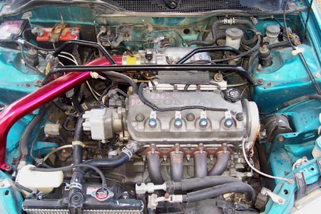
This is an AEM Twin Fire install into a 92-95 Honda Civic SOHC with an AEM EMS 30-1000 (only two coil outputs) for the purpose of converting to distributor-less ignition, aka coil-on-plug, coil-over-plug, DIS, COP, direct fire.
Benefits
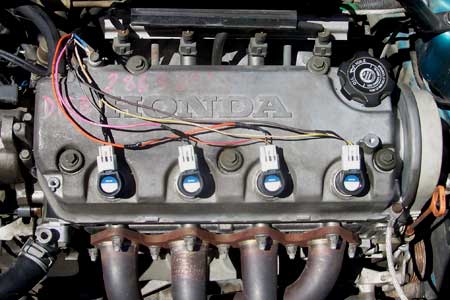
Direct Fire means that you're running one coil per cylinder. These small coils fit right on top of the valve cover. The benefit is that each coil gets 4 times as long to charge. These coils are much more powerful than the stock internal coil. You eliminate many maintenance parts prone to wear and failure including the internal coil, ignitor, rotor, distributor cap, and plug wires. The elimination of these parts increases performance, precision, decreases maintenance, operating cost, and ensures that the ignition system is always in top shape.
The EMS cannot fire the coils directly. A CDI is required (in this case an AEM Twin Fire). But there are huge benefits to running CDI vs the stock ignitor. The Twin Fire has two capacitors built into it which gives you twice the voltage and amps to the coil. This results in upwards of 50,000 volts at the spark plug vs 25,000 with the stock ignition. The CDI produces its full energy all the way past 10,000 RPM. The CDI fires the spark plug multiple times over 20 degrees of crank rotation.
Direct Fire / Waste Spark
Running direct fire requires four coil outputs from the ECU. The early EMS (30-1000) only had two coil outputs. It's still possible to run direct fire by wiring the coils in two pairs and firing them twice per engine revolution; once on the compression stroke, and once on the exhaust stroke.
Waste Spark means that you're firing the coil at the proper time, and firing a wasted spark at the opposite time. This wasted spark has no effect on engine operation except to possibly burn any incompletely burned mixture on its way out the exhaust valve. The wasted spark is not perceptible to the driver. The only drawback is that you only get twice the charge time as the stock coil.
Mount the CDI Module
Set the jumpers on the box before you mount the CDI but mount it so the switches are accessible. From left to right it should be UP, DOWN, UP. Or Switch 1 OFF, Multi-Strike Disable (except when you're checking timing with a timing light), Switch 2 ON, Trigger Edge, Falling Edge (wired directly to ECU), Switch 3 OFF, Wasted Spark, 360 Firing.
| Switch 1 | OFF |
| Switch 2 | ON |
| Switch 3 | OFF |
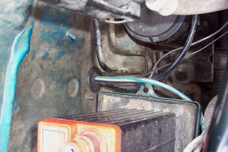
I used metal tapping screws to mount the AEM Twin Fire to the frame rail below the battery.
Wiring
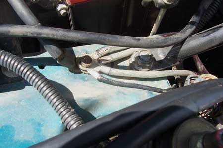
I had previously beefed up the factory battery ground on the passenger side strut tower with my own 8 gauge wires ran to the thermostat housing, starter housing, and distributor. So this is where I grounded the Twin Fire.
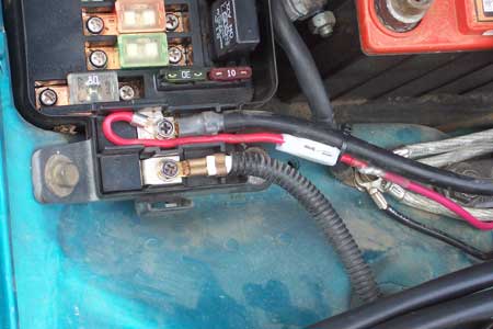
I cut a small path next to the battery positive connection to the under-hood fusebox to fit the Twin Fire's battery connection.
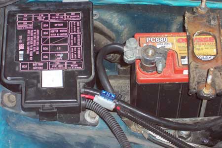
AEM didn't include a fuse holder with their Twin Fire for some odd reason, so you'll have to source one on your own. It needs to be 10 gauge with a 15A fuse and you'll also need a 10 gauge small diameter ring terminal. DO NOT USE A CIRCUIT BREAKER.
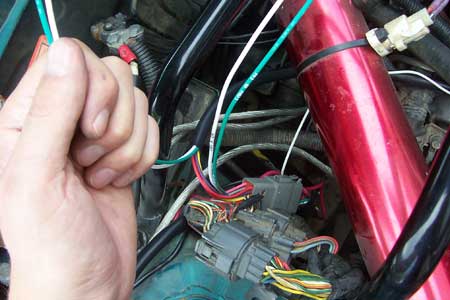
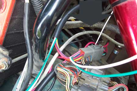
Since the Green and White wires will be going directly to the EMS, I separated them from the rest of the bundle that will be going to the distributor.
Then I slipped them into some clear heat shrink and ran them through the firewall grommet below the battery.
I pulled out the EMS and pinned some wires to B3 and B4 (coil 1 and coil 3 spare outputs on the 30-1000).
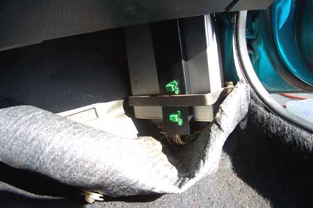
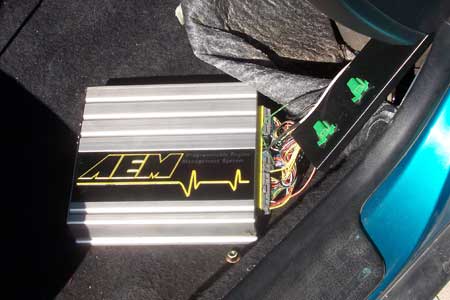
This is how I have my EMS mounted with a piece of strap metal that I cut, bent, and drilled.
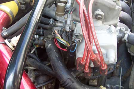
The two smaller gauge red wires go to ignition power. This is the 10 gauge black/yellow wire at the two-pin connector at the distributor. Cut the solid blue wire on the same connector and connect the car-side to the Twin Fire's white tach output wire.
The Violet and Yellow wires must be grounded. I chose to ground them at the distributor housing where one of my aftermarket 8 gauge grounds is.
Despite conflicting information I found on the internet, the correct way to wire the coils is in parallel. The Twin Fire's directions are for direct fire but not waste spark, so note that the wiring is different. Coil 1 and 4 are paralleled, and coil 2 and 3 are paralleled.
| Tan | Coil 1 and 4 power (black/white) |
| Brown | Coil 1 and 4 ground |
| Pink | Coil 2 and 3 power (black/white) |
| Orange | Coil 2 and 3 ground |

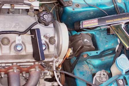
Gut the Distributor
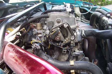
This is the gutted distributor. I put the cap back on afterwards to cover the cam sensor. Obviously this is not required and not recommended until you have this set up and running reliably. Both the AEM Twin Fire and the MSD DIS4 have been known to fail, so it may be wise to make it easy to convert back to stock ignition.
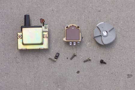
These are all the parts that can be removed: Coil, ignitor, rotor. I forgot the plug wires.
I apologize for the bright red intake and yellow coupling.
EMS Internal Jumpers
30-1000 PCB.jpg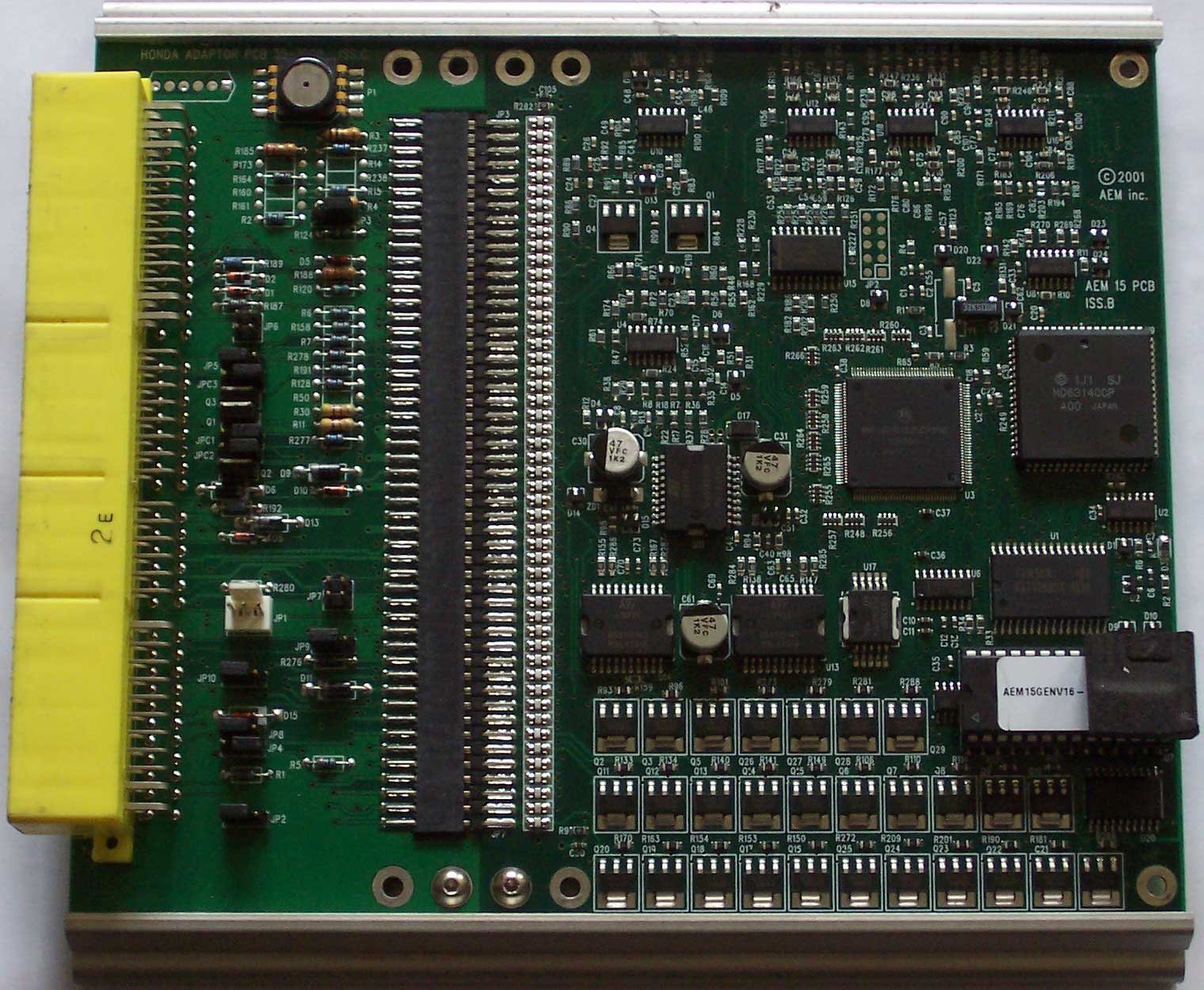
Click the above link for a full size image of the pcb.
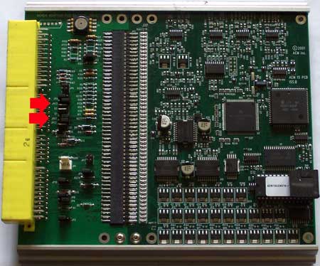
Two jumpers need to be set inside the AEM EMS 30-1000. They are JPC1 and JPC3, and they correspond to B4 and B3. The left two pins are for direct fire and the right two pins are for stock ignition. I recommend that you send the EMS to AEM and have them do it. That way you don't void the warranty. Even if it's not under warranty, once that warranty sticker has been torn, they will automatically charge you $50 just to look at it if you ever send it in. They charge you because they have to go through and check everything. The reason I know this is because my EMS had two burnt coil drivers and had to be repaired.
Configure the EMS (V1.19)
You will have to change the following settings in the EMS. I made a template so you wont have to dig up all the menus. The only thing you will need besides these is to run the coil dwell wizard. If you have to do it manually then follow the instructions below.
Ignition, Advanced Ign, Coil Dwell Setup, Coil Dwell Wizard, All CDI Systems 3ms Charge Time (Except Ford TFI)
Waste Spark TemplateIf you're using my template, note that your Ignition Sync and Injector Phase will vary from mine.
Put this file in your AEM folder and then go to Templates, Run.
Options, Coil. Make Coils 1, 3, 6, 8 Active.
Setup, Sensors, Cam/Crank Sensor, Cam/Crank Setup. Spark Teeth 24. Check Crank Alt Fire (optional).
Ignition, Advanced Ign, Ignition Phasing, Options Ign Phasing:
| Ign Tooth #01 | 0 |
| Ign Tooth #03 | 6 |
| Ign Tooth #06 | 12 |
| Ign Tooth #08 | 18 |
Ignition Timing
Checking your base ignition timing advance is a little different now that you've converted to waste spark. Now that your coils are firing twice as many times per cylinder as your one coil used to, your timing light is going to read double. You wont be using a static timing light to line up the red line with the pointer on the timing belt cover anymore. You'll need an adjustable timing gun so that you can turn the knob to line up the white tdc mark instead. Cut the number on the knob in half and that's your timing.
Configure, ECU Setup, Set Ignition... and then correct the EMS to match the timing indicated by a timing light. This is the procedure that you did when you first installed the EMS and it's the reason why your Ignition Sync will vary from mine. You need to adjust this any time you move the distributor. You hook up your timing light the same as usual except you clamp onto the positive black/white wire only.
Wait until the engine is idling at a steady ignition timing. You may have to temporarily zero out your Ign vs Idle table. Then hit Advance or Retard and watch how it effects the Ignition Sync parameter. When the tdc mark gets close, switch to Fine and get it dead on. You may find it easier if you turn switch 1 on the Twin Fire ON to disable multi-strike.
Finishing Touches
Now that it's up and running and somewhat driveable, you can go back and split loom all the wiring and tape it up. Just remember to leave coil 1's positive wire accessible so you can check the ignition timing when you need to.