
- Home
- The Basics
- Stealth Installs
- Misc Security
- Kill Switches
- Convenience
- Modifications
- Maintenance
AEM Gauge-Type UEGO Controller 30-4100
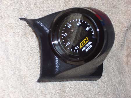
(ebay gauge pod)
Install into OBD1 Honda/Acura
This article is meant to supplement but not replace the instructions provided by AEM.
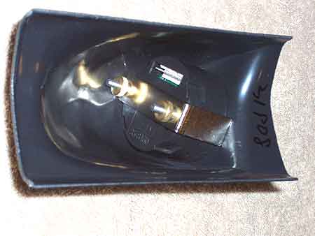
Both the gauge and the pod were purchased from ebay. The pod is good quality; very thick durable plastic, a perfect fit for both the gauge and the A pillar; which is surprising because there is no name brand and the shipping was more expensive than the pod itself. The gauge was cheap and shipped quickly, as is typical of ebay, but don't expect any customer support if you run into a problem. You take a gamble buying from ebay. Spending more at a store front may save you money in the end. It's up to you.
Wideband O2 sensor vs Standard "narrow" band
A standard oxygen sensor (like your original oem or aftermarket replacement sensor) is accurate measuring a 14.7 stoichiometric air fuel ratio. When connected to an air fuel ratio gauge, it can give you advance warning to let off if you run lean under heavy throttle, which could save your motor. It can tell you if you're running rich or lean, but unfortunatley, it can't tell you how rich or lean. A standard O2 sensor doesn't know if you're running 10:1 or 13:1, so it's not useful for tuning the air fuel ratio. If you want your engine to run 12.2 in closed loop with O2 feedback, you need a wideband.
Benefits to Running a Wideband on the Factory ECU
Running a wideband on your factory ECU will have absolutely no affect on your peak horsepower. That is because at wide open throttle, your ECU goes to a predetermined fuel map and ignores input from the O2 sensor. Emissions and fuel economy benefit because it is much easier for the ECU to keep up with a wideband than it is for it to constantly chase a standard O2 sensor which rapidly bounces back and forth from lean to rich. The real benefit to running a wideband on your OEM ECU is that it will teach you what a good tune air fuel ratio looks like (assuming your motor is close to stock).
Beginners often believe that a car runs either rich or lean. They don't realize that all cars run rich, stoich, and lean depending on different parameters. At warmup, the mixture is very rich. At idle, Honda runs stoich to 15.5. Under moderate acceleration, you'll see 14.7 to low 14's. Cruising at high speed with low load will show stoich. When cruising with very low load, the engine runs mid 13's. When decelerating with no throttle above about 1000 RPMs, the injectors shut off so the mixture is too lean to read. Decelerating below 1000, the mixture is lean with the injectors barely coming on as it prepares to idle. At WOT, the mixture goes rich. Over time you start to develop an understanding of where the mixture is for different amounts of throttle and different RPM. One day this will become the basis for you to create your own fuel maps using an aftermarket engine management system like the AEM EMS.
Install it Right
At the forums on AEM's site, there are hundreds of articles from people who are having problems with their gauge. Many of these threads go unanswered because chances are the gauge simply isn't installed correctly. Even if it works initially, a bad install will lead to premature failure. This article outlines a very clean, reliable install.
No fuse taps, no duct tape, no masking tape, no speaker wire, no wire nuts, no scotch locks, no t-taps.
- Tools
- Drill
- Angle Driver
- 3/4 inch Hole saw
- Phillips bit
- Wire wheel bit
- Ratchet
- 10mm socket
- Oxygen Sensor socket or wrench
- Grappling tool
- 100 watt soldering gun
- Channel Lock 909 crimpers
- jeweler's flathead screwdriver
- Razor Knife
- Wire cutters
- Wire strippers
- Pick
- Supplies
- Metal tapping screw short
- Screws short x4
- Speed clips x4
- 18 gauge ring terminals x3
- 18 gauge female quick disconnect or "option" plug
- Inline fuse holder
- 10A automotive fuse
- .040 or .032 solder
- Split loom small diameter
- 18 gauge wire, prefer. 3 different colors, prefer white, red, black
- Zip ties
- Electric tape
- 1K resistor (brown, black, red, gold)
- 8 gauge wire 3 feet
- 8 gauge ring terminals x2
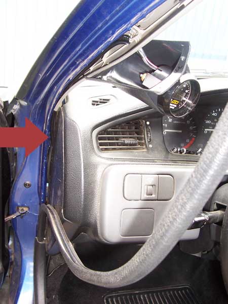
Prep the A Pillar
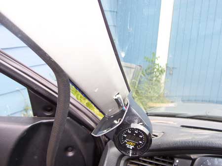
First hold up the gauge pod to the A pillar and decide where you want to mount it. I chose to mount it at eye level and on the same plane as the steering wheel.
Peel the door seal back so you can see the pressure clips holding the A pillar. Pop these clips using a panel popper. Drill a 3/4 inch hold in the center behind where the gauge pod will be mounted. Be careful not to damage the factory wiring running up the A pillar. Also check to see what's on the other side of your hole before you drill it out.
Run the harness with the white, blue, red, and black wires through the hole leaving a few inches for slack but not so much that it can't be tucked under the gauge pod. Run this wire down and inside the dash above the fuse panel.
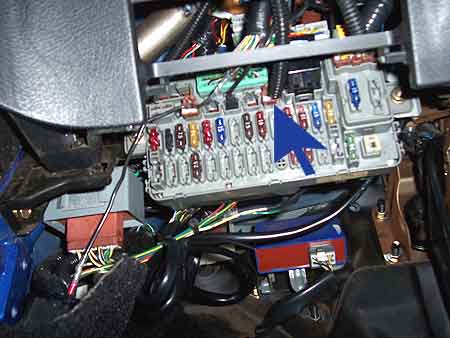
These are the fusebox outputs for a 92-95 Civic and 94+ Acura Integra. 88-91 Civics, 96-00 Civics, and 90-93 Integras have similar outputs on their fuse boxes. Verify the outputs with a multimeter. The meter should show no voltage with the key off, and roughly 12 volts with the key on, engine off. It should show 12 volts with the engine running. This is where you will connect the AEM's red wire (to either of the fuse outputs shown in orange). You can connect a wire to the fusebox option output using a female quick disconnect.
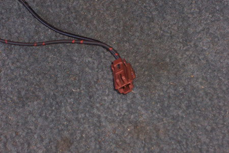
A fuse box option connector can be used instead of a female quick disconnect. These little brown plugs can be found in the driver's door on 92-95 Civics and 94+ Integras that have power door locks. I've also found them near the AC on 94+ Integras. Make sure to get a one-pin plug connector.
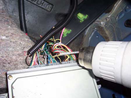
Red

Cut a small slit in the black tubing and carefully pull out the gauge's red wire using a pick tool. Solder and heat shrink this wire to an inline fuse holder and insert a 10A fuse. Solder/heatshrink the other end of the inline fuse holder to the option plug if you have one, or just crimp on a female quick disconnect. Plug this into an accessory output of the fusebox (shown in purple). You could alternatively tap into the 10 gauge black/yellow wire at the fuse box or the ignition harness (of any Honda/Acura).
Black and White
Extend the gauge controller's white and black wires and run them all the way to the ECU.
Blue
Crimp a wire cap onto the gauge controller's blue wire. Tuck all the wires into split loom and secure the beginning of the split loom to the black tubing using electric tape pulled tightly.
Install O2 Sensor
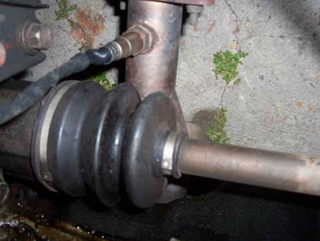
Remove your old O2 sensor using the O2 sensor socket and put it in a safe place. Install the wideband O2 sensor. In this case, I had a DC header with the O2 sensor relocated just before the cat. Other cars may have the O2 sensor right on the exhaust manifold.
Run Wires Through Firewall
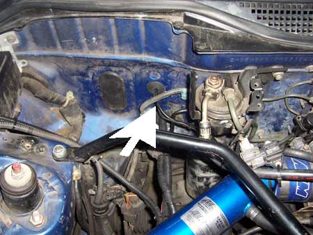
Run the O2 sensor harness through a grommet in the firewall. In this case I actually drilled a new hole using a hole saw and plugged it with a grommet I had taken from the junkyard.
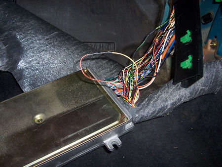
Route/Secure Harnesses
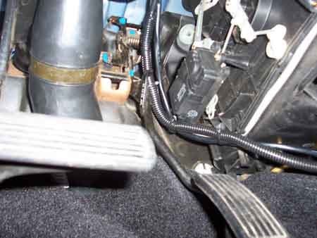
Run the two harnesses and the wiring behind the dash and up the A pillar and out the hole you drilled. Secure the harnesses with zip ties away from moving parts such as the pedals and climate control system.
Gauge Controller Signal Output
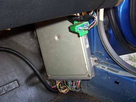
Cut the white/red O2 sensor input at pin D14 and connect the gauge's extended white wire to the ECU side. The other side is no longer used.
Ground
It's very important that you use the sensor ground provided by your ECU. If you use chassis ground, your O2 readings will be slightly inaccurate. You can use pin D21 or D22.
Preventing Code 41 "O2 Sensor Heater"
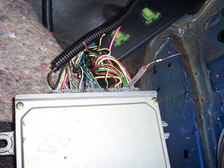
Cut the orange/black O2 sensor heater wire at pin A6 and solder a resistor between 10 and 40 ohms onto the ECU side. Slip some heat shrink tubing over the resistor and wire. Cut the yel/blk wire at pin A25 and solder the ECU side to the other end of the resistor. You can leave the engine side of both wires hanging. Shrink the tubing. This prevents your ECU from throwing a code 41, "O2 sensor heater malfunction".
ECU pinout ReferenceAdjust Gauge Controller's Voltage Output
Using the jeweler's screwdriver, turn the adjustment knob on the back of the gauge all the way clockwise to p04 for OEM ECU 0-1 volt output.
Final Mounting
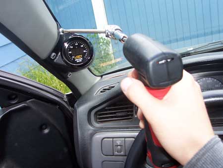
Mount the gauge pod to the A pillar using short screws. I put screw caps over them for a cleaner look. You'll need an angle driver to get to the rear screws.
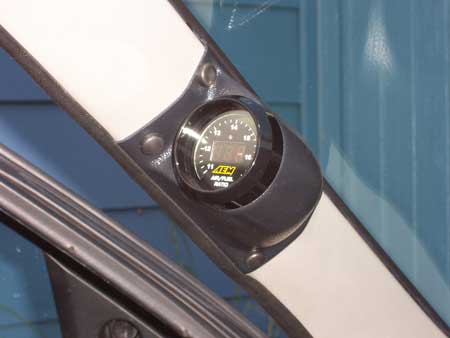
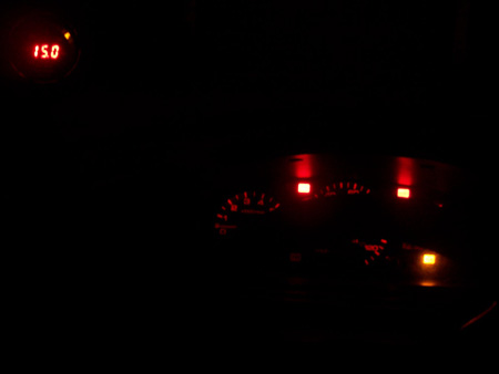
When you power up the gauge, it will go through its test sequence 1-9, it will verify that it's set to p04, then if your engine is cold it will show 15.7. If it doesn't say p04, adjust the knob on the back of the gauge.
Reset ECU
Reset your ECU by pulling the 7.5A backup fuse under the hood and flashing the brights to remove any surface charge.
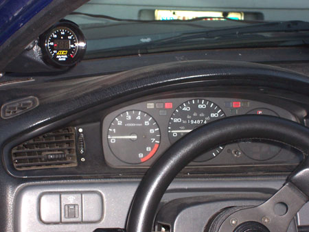
I intended the end result to blend easily with the factory cluster. I went so far as to replace the cluster's original bulbs with red wide angle LED's.
The End