
- This Page
- How to Crimp
- Connecting to a Switch
- Connecting to a Relay
- Relay Spike Suppression
- How to Solder
- Tap Into Existing Wire
- Secure Split Loom
- Locating/Verifying Wires
- Fuses
- +/- Switching
- Verify Door Trigger
- Verify Parking Lights
- Verify Starter
- Verify Ignition
- Verify Constant 12v
- Verify Ground
- Verify Door_Locks
- Verify Fuel Pump
- Fusebox Outputs
- Home
- The Basics
- Stealth Installs
- Misc Security
- Kill Switches
- Convenience
- Modifications
- Maintenance
The Basics
This page contains all the information you need to understand the site and perform basic tasks such as soldering, crimping, hooking up relays, and using a multimeter.
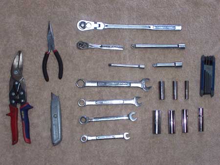
This is a list of my most commonly used tools and supplies, specifically the tools/supplies I used in the projects on this site. Not all of them are necessary, and some may be beyond your budget. But the more tools you have, the more you are capable of and the cleaner your install can be. Having the right tools and supplies is half the job.
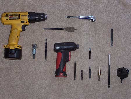
- Tools
- Cordless Drill
- Angle Driver
- Wood Spade Bits
- Wire Wheel
- 9/32 Drill Bit
- Electric Screwdriver *optional
- Phillips Adapters
- Socket Adapters
- Unibit
- Extensions
- Hole Saws
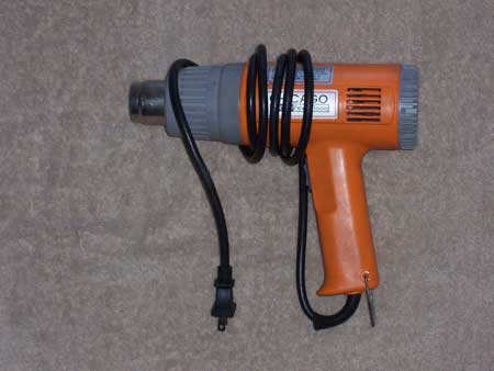
- Heat Gun (if using heat shrink or double sided tape)
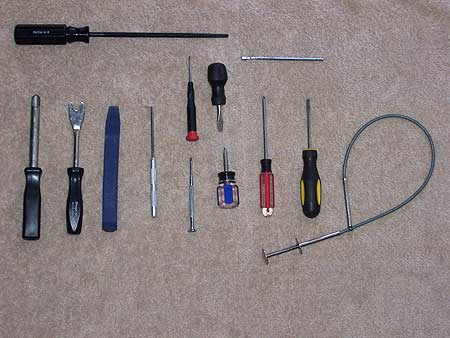
- File
- Magnet reaching tool
- Wire Insertion Tool
- Panel Poppers
- Angle Pick
- Jeweler's Screwdrivers
- Stubby Screwdrivers
- #2 Screwdrivers
- Grappler
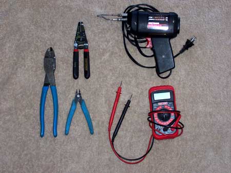
- Channel Lock 909 Crimpers *yes, these EXACT crimpers
- Wire Strippers
- Wire Cutters
- Soldering Gun 140/100 watt (Radio Shack, Craftsman, Weller)
- Digital Multimeter
- Snips
- Needle Nose Pliers
- Razor Knife
- Ratchets
- assorted Extensions
- Wrenches 8, 10, 12, 14
- Sockets 8, 10, 12, 14
- T40 Torx Bit *some 4th gen Civics/CRXs
- Scissors
- Supplies
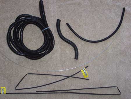
- Split Loom various diameters
- Heat Shrink Tubing various diameters
- Non-insulated Butt Connectors
- Zip Ties
- DEI sensor plug (scavenged from junkyard)
- Various Screws, metal tapping, etc
- Grommet
- Wire Bundle Clip
- Screw Caps
- Speed Clip
- Lock Washer 'star washer"
- 1 Amp Diode
- Wire Cap
- Female Quick Disconnect
- Male Quick Disconnect
- Ring Terminals various gauges/diameters
- Spade Terminal
- Option Clip (scavenged from junkyard)
- Backstrap
- Double-sided Tape
- Electric Tape (the good stuff is stretchy)
- Spools of 18 Gauge Wire
- Spool of Solder .032 or .040
- Hood Pin
- Inline Fuse Holder
- Long Zip Tie (riot cuff)
- SPDT Auto Relays
How to Crimp
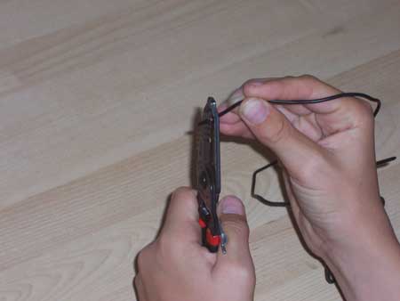
Strip the wire back 1/4th of an inch.
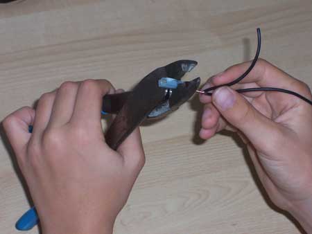
Align the dimple on the Channel Lock 909s with the seam on the quickdisconnect. Insert the wire into the quick disconnect so that the wires passes through cleanly and the insulation butts up against it. Then squeeze.
Other brands of crimpers may look similar to the Channel Lock 909s, but the Channel Locks have a little dimple instead of a perfect half moon. The dimple and the leverage are what makes for consistent perfect crimps.
Connecting Wires to a Switch
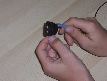
Quick Disconnects slip right onto the pins of most aftermarket DC 12V switches.
Connect Wires to a Relay
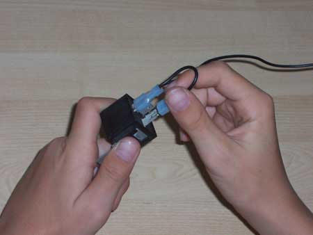
Quick Disconnects slip right onto the pins of DC 12V relays. I recommend Bosch brand relays. They also fit the option outputs on under-dash fuse panels. They also slip right onto the starter input.
Relay Spike Suppression
You can increase the reliability of your relays by using a diode for spike suppression. You can do this on any relay application. The diode must bridge 85 and 86. The striped end of the diode MUST ABSOLUTELY be connected to the power side, and the non-striped end MUST BE CONNECTED to the ground side. This is the opposite of how diodes are most commonly used.
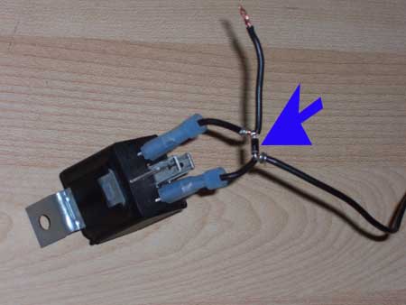
This method is quick and dirty if you want to throw a diode on an existing relay w/out re-doing the quick disconnects. Strip the wires, twist the diode ends, solder, then tape it up.

This is a cleaner method. Simply crimp the diode in the quick disconnects with the wire.
How to Solder
For automotive wiring, you'll want a 100-140 watt soldering iron with a trigger and a light. You'll want a tip that is small but has a nice flat end on it. You'll want to use .040 solder (.032 can be useful for soldering 10 gauge wires). Portable butane irons are also useful, but you may find it tedious to constantly ignite it only to shut it down for a few minutes.
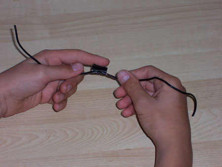
Strip the wire back about 1/2 of an inch.
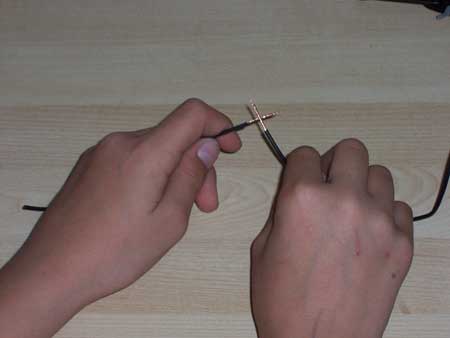
Cross the wires and then twist them together one at a time so that you have a smooth inline connection. Any sharp edges will later protrude from the tape and cause a short.
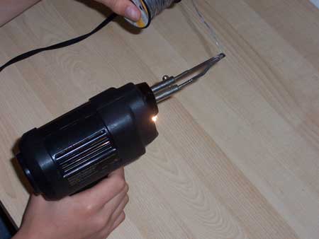
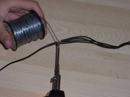
Clean any dark or dull deposits from the tip of the soldering iron using a wire brush. Then heat it up for about 15 seconds, then coat the tip with a very thin layer of solder.
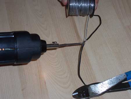
Place the wire on top of the hot tip of the soldering iron and wait about 10 seconds for the wire to heat up (longer for thicker gauge). Touch the solder to the top of the wire and it should start to melt and soak into the strands. Soak in just enough solder so that the connection is shiny but the individual strands should be visible.
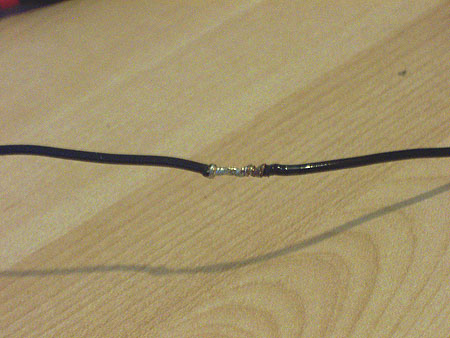
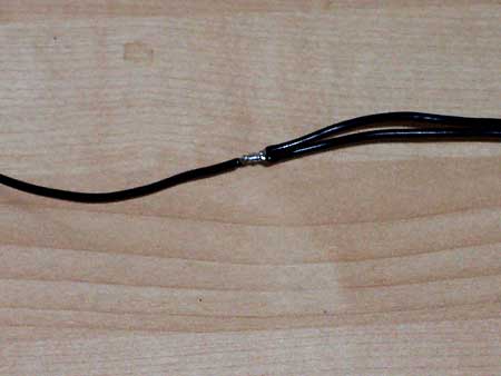
This is roughly what your connection should look like. don't use too much solder.
Start the electric tape on the insulation beside the connection. Wrap the tape diagonally and stretch it tight for good adhesion and to eliminate any air gaps.
Tap Into a Wire
Connecting to an existing wire in the vehicle is a little different than joining two cut ends. There is no need to cut the wire.
Strip the insulation back a little more than 1/4 of an inch. I find it easiest to cut the insulation with the stripping tool, then push the insulation back with my little blue wire cutters. Twist your wire end around the bare wire so that your wire lays parallel against it. Solder and tape the connection as normal.
Secure Split Loom
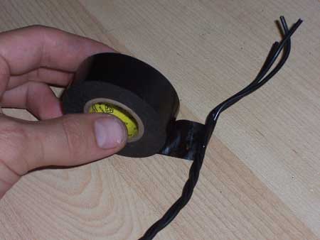
Start the tape on the wire. Stretch it nice and tight.
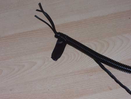
Slide the slit loom up the wire so that the tape protrudes out the slit. Then wrap the tape around the split loom for about an inch or wrap the entire loom if you want.
Locating/Verifying Wires
Before I can tell you how to verify a wire using your multimeter, I have to teach you some concepts. There's not a lot of electrical theory here, just the basic idea as it relates to what we're trying to accomplish on this site.
Circuit
You never need two switches on the same circuit, but two are illustrated here to demonstrate both types of switching.
This abomination is my diagram of a circuit. Power flows from the battery positive, to a load, to the battery negative. If you don't have a load, bad things happen. If there's a fuse, then the fuse blows. If there's no fuse, the wire heats up, the insulation melts off, then your car catches on fire. If at any point between the battery and the load the wire is grounded, then the power is going to flow directly to ground and start a fire.
Fuses
Fuses are a good thing. They prevent your car from catching fire and your components from burning up. The higher the fuse rating, the bigger the spark before the fuse blows. You want to use the lowest rating fuse possible. If you use a fuse rating lower than the amount of current your load draws, then the fuse will blow and the circuit will never work. I recommend using the highest amps your load can handle for a brief second without damaging it. If you have more than one load on the same wire, you should use a fuse appropriate for the length and gauge of the wire and then each load should have its own fuse where they branch off. The fuse must be within a few inches of the battery to protect the wire. Any length of wire between the fuse and the battery is not protected.
If the negative side of the load is grounded, who cares? You can't "short" the negative side.
Negative and Positive Switching
I didn't mention the switch. A switch isn't necessary, but it allows control of the circuit. You can have the switch on the positive side or the negative side of the load, but you don't need both (like shown in the diagram). I prefer negative side switching when given the choice. There's less of a risk of a short if anything goes wrong with the switch connections (see end of preceeding paragraph). The switch can be a toggle switch or it can be a relay (which is a type of switch controlled by an electromagnet). Whether the circuit is positive or negative switched is going to determine how you verify a wire. On Japanese cars, and most cars other than Fords, most of the wires we will be concerned with are negative triggered.
If you set your meter to 20V DC, ground the black proble and put the red probe to the bare metal of the wire between the battery positive and the load (pretend the switch isn't there), it will be the same as testing the battery positive directly. There's no point.
Testing Positive
So when testing a positive switched circuit, you'll be metering after the switch and before the load. Set the meter to 20V DC and put the black probe to chassis ground and the red probe to the suspected wire. Voltage will be zero, then you flip the switch (ie crank the starter) and it will be 12 volts.
Testing Negative
When testing a negative switched circuit, you'll be measuring between the load and the switch. Set your meter to continuity, ground the one probe to the chassis, and touch the other probe to the bare wire. The meter should read infinite resistance (shown as a "1"). When you close the switch (ie pop the trunk), your meter should show 0 resistance (most meters will make a sound).
Verifying Wires
Door Trigger/Dome Light
Door triggers are negative trigger. Typically you want to tap into the passenger side door trigger wire because it 'sees" all doors, while the driver's side does not. Hondas/Acuras trigger the domelight by grounding the door trigger wire, and so will your alarm.
Trunk Trigger
Verifying the trunk trigger wire (negative trigger) is the same as the door trigger wires. There are typically multiple wires of the same color in the same bundle as the trunk trigger.
Parking Lights
You shouldn't have to verify the parking light wire since it is any 18 gauge red/black wire in the car. Parking lights are positive trigger. Connect your meter to the suspected wire and it should read 0 volts. Then rotate the combination switch on the steering column one click and it should jump to 12 volts.
Starter Wire
Starter wire is also positive trigger, and it also shouldn't have to be verified because it's the only 10 gauge black/white wire in the car. In some places it changes to black/red on manual transmission equipped vehicles.
Ignition
Ignition is positive trigger. It's always a black/yellow 10 gauge wire. Trigger by turning the key clockwise two clicks. The meter should jump to 12 volts. It should also be 12 volts while you are cranking the starter. If it drops to 0 while the starter is cranking, it's an Accessory or Ignition 2 wire and is incorrect for an ignition input to the alarm.
Constant 12v
A constant 12v source will always show 12v (or close to it) regardless of key position or whether the engine is running. If the car has been sitting a long time, it may read as low as 10 volts. If the engine is running, it may read 13.8 to 14.4 volts (indicating the alternator is charging).
Ground
You can verify a ground by setting your meter to continuity and putting a probe to a known ground, like the key cylinder or door striker, and the other probe to your suspected ground wire or chassis ground. You can also set your meter to 200 ohms and test your ground against a wire ran from the negative battery post. Ideally there should be no resistance.
Door Lock/Unlock
Honda/Acura uses low current negative pulsing for its door locks. Your meter will show a change, but is too slow to keep up with a quick pulse. The trick is to hold down switch while testing the wire. You can further verify door lock/unlock wires by testing whether the switch works after you've cut the suspected wires. Another way to double verify is to temporary connect the suspected wire to an inline 7.5A fuse and tap it to ground.
Fuel Pump
The fuel pump is positive switched. It primes for a second when you turn the key to the ignition (not in ACC). Your meter will jump from 0 to 12 volts while you hear the click-whirr, then drop back to 0. When the engine is running, the wire will show 12 volts.
Fusebox Option outputs
Red constant 12v, Purple accessory, White parking lights
You can tap into these under-dash fuse panel outputs using a female quick disconnect or a single pin honda brown connector.
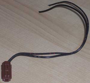
You can scavenge these plug connectors from inside the driver's door on EG and DC Integras with power door locks or from the engine bay near the AC on DC's.