
- This Page
- How it Works
- Helms Manual Page Numbers
- Installation
- Swap Pedal Assemblies
- Cruise Actuator
- Cable Bracket
- Auto Cruise Module
- Cruise Switch
- R/A S/D Switch
- Wiring
- Cruise Switch
- Behind Cluster (VSS, Tach, Cruise Light)
- Brake Switch
- Clutch Switch
- Under Dash Fuse Box (Accessory 12V)
- Cruise Actuator
- R/A S/D Switch
- Wire Color Tables
- Auto Cruise Module
- Cruise Switch
- Cruise Indicator Light
- Cruise Actuator
- Finishing Up
- Test Auto Cruise Module Harness
- Home
- The Basics
- Stealth Installs
- Misc Security
- Kill Switches
- Convenience
- Modifications
- Maintenance
OEM Cruise Control Swap
This is how you swap factory cruise control into a 92-95 Civic or 90-01 Integra that came without it. The 92-95 Civic and 94-01 Integra parts are all interchangeable.
All of the factory cruise control wiring is entagled in the SRS harness and the interior harness. Cars w/out cruise control have none of this wiring and it's impractical to swap the entire harnesses. Tinkering with the SRS harness can be dangerous. This how-to shows you how to wire it all from scratch.
Reader Contributions
Fan feedback inspired me to finish it and revise some of the info. Big thanks to Blair Dillman from Rochester NY, Photobucket. A second contributor wishes to remain anonymous. C.A. provided some helpful feedback leading to clarifications. Keep it coming, folks!
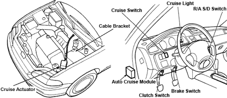
How It Works
Some cruise control systems operate by vacuum. Some are connected to the throttle body with a cable. In this case, Honda connected the actuator cable to the gas pedal. A small ECU in the driver's kick monitors the vehicle speed sensor, as well as the tach input from the distributor coil. A master switch enables the whole system, while steering wheel mounted controls allow the driver to select the speed to maintain. And finally, there are inputs from the brake pedal and clutch pedal to disable the system whenever either pedal is pressed. All of this is independent of the Engine Control Unit.
Models that came w/out cruise control lack the bracket on the throttle that the actuator cable connects to. Also, the switch on the brake pedal has four pins instead of just two. The throttle and brake are one whole assembly connected to the brake booster. There also is a lack of any wire harnesses for the cruise control system. The OEM steering wheel has no provision to mount the control switch. The dash has a blank panel that can be removed so that the cruise master switch can drop right in.
Helms Manual
These are the pages (pdf) in the Helms manual that cover cruise control.
- Electrical Index 23-1 p941
- Cruise Control 23-252 p1190
- Instrument Cluster 23-130 p1070
Parts Required
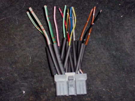
These are the parts you need to get from a cruise control equipped vehicle. Make sure you get the hardware for the parts shown and get both sides of each wire harness. You have to cut the plugs off from the dash harness so make sure to get as much length as you can.
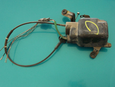
Cruise Actuator
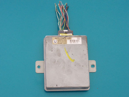
Auto Cruise Module
Integra and Civic modules are interchangeable even though a sticker on the module specifies an ECU code.
Module Bracket
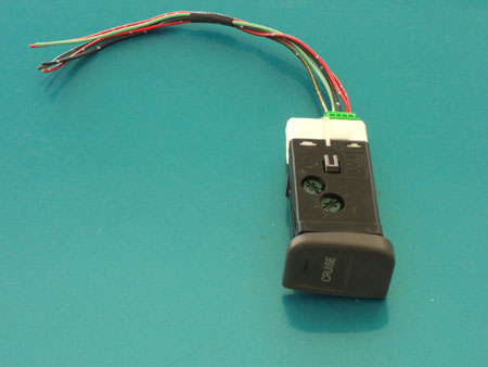
Cruise Switch
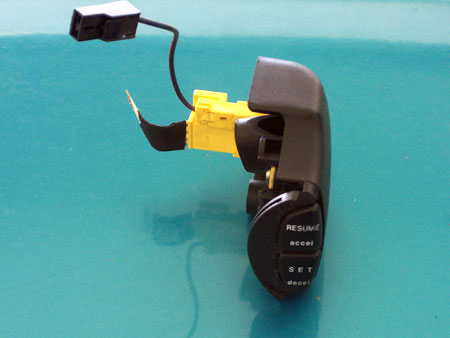
Resume/Accel, Set/Decel Switch or aftermarket off-on-off momentary rocker switch.
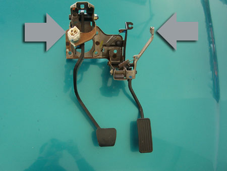
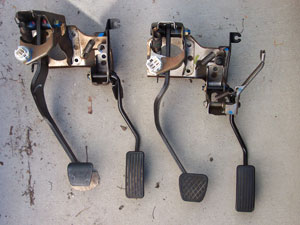
Gas and Brake Pedal Assembly
Note that I forgot the four pin brake switch harness and had to go back for it later.
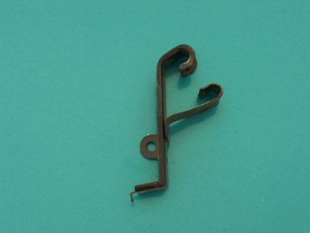
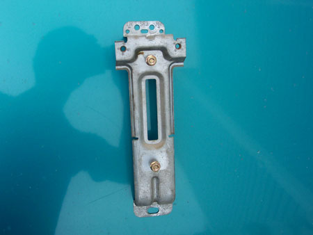
Throttle Cable/Cruise Cable Combo Bracket
Some models lack the lower clutch cruise control switch so check if you need one.
Cable Reel and yellow plug connector from steering column. You need the lt grn/black and lt grn/red wires de-pinned from this harness.
If you have a non-tach instrument cluster and you want the cruise indicator light, you'll need an EX/LX/Si cluster and the little green harness that plugs into it.
- Supplies
- 18 gauge wire, multiple colors preferred
- solder
- electric tape
- small cotter pin
- Tools
- Ratchet
- 19mm socket
- 10mm Socket
- 10mm Wrench
- 12mm Shallow and Deep Sockets
- T-30 Torx Bit
- Long and Short Extensions
- Straight Pick for de-pinning wires
- Hook Pick for pulling the cotter pin
- Phillips Screwdriver
- Flat Blade Screwdriver
- Panel Popper
- Wire Cutters
- Wire Strippers
- Soldering Iron
- De-Soldering Tool
- Digital Volt Meter
- Drill
- Holesaw
Installation
Mounting the components is easy. The only physically difficult task is swapping the gas/brake pedal assembly.
Swap Pedal Assemblies
Drop the Steering Column
To get the pedal assembly out, it's necessary to drop the steering column. You don't have to completely remove it, so don't take out the pinch bolts at the rack. Remove the clips and the black cover.
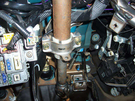
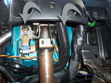
Remove the two inside bolts first, then remove the outer bolts while supporting the wheel. Carefully lower it to the floor.
Remove the Pedal Assembly
First remove the pin that connects the brake pedal to the master cylinder. There is a tiny cotter pin that you need to remove before you can push the joint pin out.
Remove the two 12mm bolts. One is just above the throttle, and the other is above the column holding the brake pedal bracket. Then remove the four nuts above the brake pedal that hold the brake booster. On the engine bay side, pull the brake booster forward until everything clears the firewall. Use a bungee cord or something to hold it in place.
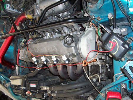
Next disconnect the throttle cable from the throttle body. It isn't necessary to remove the bracket holding the sleeve, we just want some slack on the cable itself so we can disconnect it on the gas pedal side.
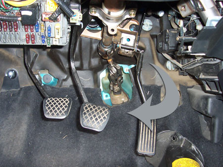
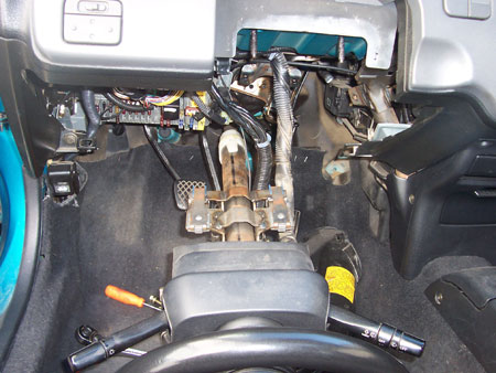
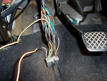
(Ignore the fact that the column is still bolted up in this pic.) Pull the pedal assembly forward and down. The brake switch will get hung up on the ignition wire harness so you will have to fight with it a bit. Now that they're more accessible, you can pop the tab out that connects the throttle cable to the pedal, and push in the pin and release the brake switch harness. Rotate the assembly as you lift the column so that you can get enough clearance to pull it out.
Put everything back together making sure that the throttle, brakes, and brake lights are all working properly.
Cruise Actuator
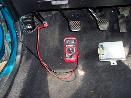
Before you run the cable through the firewall you should test the unit. You need to have access to the cable to test the actuator.
Remove the two 10mm screws holding the cover on.
Pull the actuator side of the pins out of the harness. Temporarily ground the black wire.
You'll need power to complete the test. I found it convenient to pull one of the leads out of my digital voltmeter, unplug the two-pin distributer harness, and shove the lead in the blk/yel pin. Put the key in the ignition and turn it to the third position (Key On, Engine Off).
| Firewall Side | Actuator Side |
|---|---|
| blk | blk |
| brn/blk | blu |
| brn | brn |
| brn/wh | wh |
Test One
Ground black and touch power to white. You should hear the actuator lock so you can't pull the cable.
Test Two
Ground black and blue. Touch power to brown. The actuator should push the cable out.
Test Three
Ground black and brown. Pull on the cable so the linkage is in a middle position. Touch power to blue. The actuator should pull the cable in.
The first actuator I got wouldn't move the cable. The motor inside the actuator was bad, though I could hear it click.
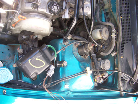
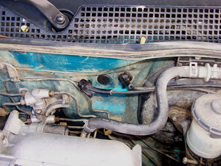
If the actuator is good, mount it to the pre-existing holes in the frame and run the cable through the bracket and through the firewall. Then connect it to the throttle pedal under the dash.
Cable Bracket
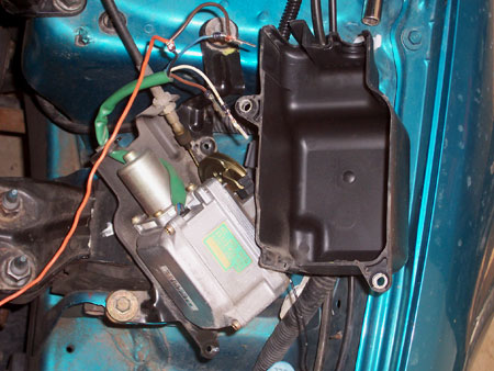
Auto Cruise Module
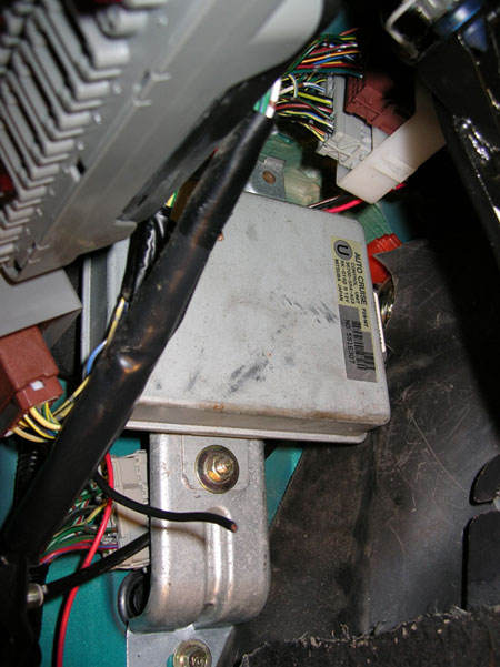
Installing the bracket for the cruise module is difficult because the dash harness is in the way of the 10mm bolt that is already highly inacessible. First install the bracket, and then install the module. Have fun.
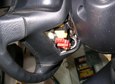
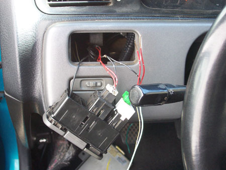
Cruise Switch
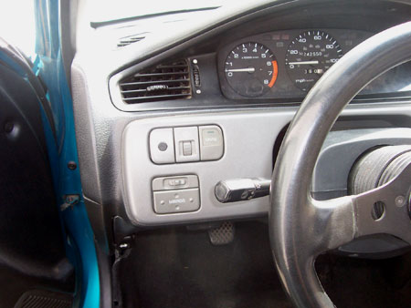
Leave the switch out until you've wired it up. Pop out the combo switch assembly by pushing from behind. Unplug the dimmer harness, then push the four clips simultaneously to release the blank panel where the Cruise Master Switch drops in.
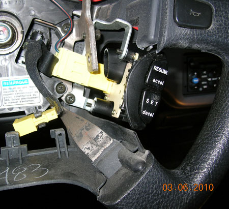
Resume/Accel, Set/Decel Switch
Thanks once again to Blair Dillman for the following contribution!
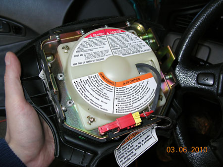
OEM Switch
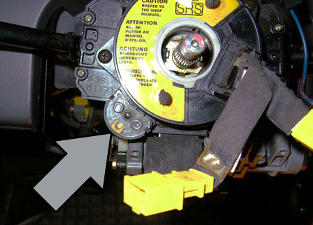
Unscrew the flap on the underside of the steering wheel, unplug the SRS harness, and plug this short connector into the airbag side. Installers have been killed by airbags so don't take this lightly.
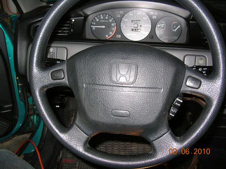
Use a panel popping tool to remove the covers on each side of the steering wheel to expose the T30 screws.
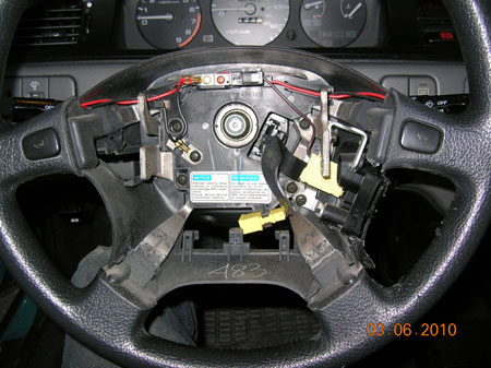
Once you have the T30's out, you can remove the airbag. Put it under the car where it can't kill anyone. Or stick it under a dumpster and set it off (shenanigans).
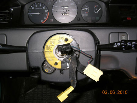
Center the steering wheel. Remove the 19mm socket and pull the wheel. Remove the screws and pull the cable reel straight off.
Swap your non-cruise cable reel with the donor cable reel. Make sure yellow alignment notch is centered and cable reel is set to top center before reinstalling wheel.
Reattach the steering wheel and connect the cruise switch.
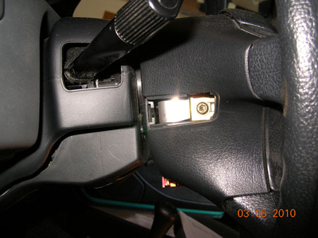
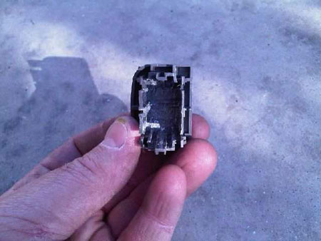
Aftermarket Switch
A fan of the site kindly contributed photos and a description of how to use an aftermarket switch. This is useful for people that have an aftermarket steering wheel.
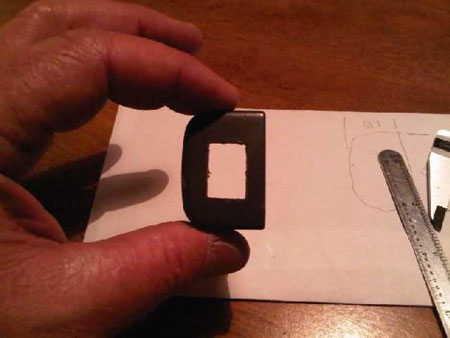
"After pulling the OEM S-D/R-A switch apart to make the modifications detailed in the ‘Cause for Alarm’ website, I realized there was a cleaner way. All the switch does is route a +12v power signal to the cruise module where it determines, based on it’s current state, whether to set the speed, decelerate, accelerate, or resume the last speed selected. A simple (off)-on-(off) momentary rocker switch would work just as well and could be placed anywhere in the vehicle. I wanted to put the switch in the blank next to the dash light dimmer so I chose a micro-sized switch from www.wiringproducts.com. The switch + shipping was less than $9. If you have a decent electronics store nearby you could have it for just a few bucks. Unfortunately Radio Shack did not carry what I needed. The switch fits perfectly in the hollowed out blank. The cut-out is .5”x.75”."
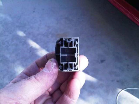
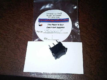
"Notice the rocker is in the middle. Pushing it to one side or the other sends power to that side. I wired it like the OEM switches; down is set/decel, up is resume/accel. The rocker is spring loaded to return to the middle. Switch is part #7500007 in case you can’t read it."
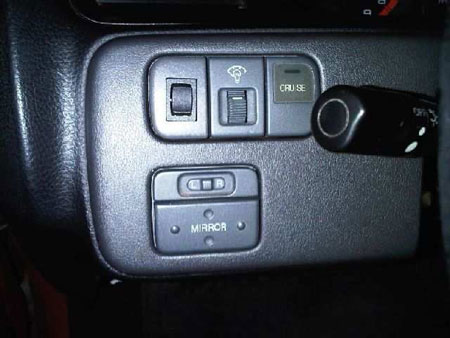
"Not the straightest or most centered but hey, it works! Note the mirror switch. I got that done from your site too!"
Once again, thank you Mr Anonymous fan of the site and congratulations on being the first person to follow through on their promise to contribute content!
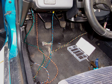
Wiring
There is a lot of wiring involved. Most of them are wired together, effectively cutting the amount of wires in half. Only a few go to the vehicle.
Cruise Switch
Three of the five wires found on the main switch can be wired color-for-color to the dimmer switch right next to it. The other two have to be extended. The two blk/yel wires connect to the under-dash fuse box blk/yel. The lt grn wire extends to the lt grn on the Auto Cruise Module and to the lt grn on the Brake Switch.
If you are swapping to a cruise cluster and want to wire the Cruise Indicator light, then wire it at the same time as the Cruise Switch.
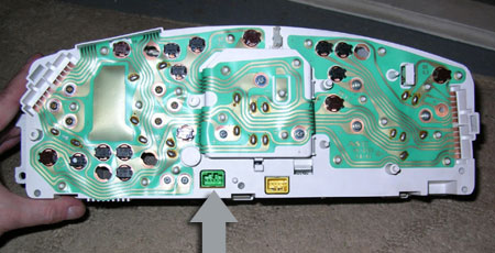
Behind Cluster (VSS, Tach, Cruise Light)
Several connections can be made behind the cluster. The tach input is solid blue D5, and the Vehicle Speed Sensor is yel/blu D11.
To use the gauge cluster Cruise Indicator light you have to swap in a cluster from a Civic that came with Cruise Control (EX, LX, Si). If you have one of the rare VX or EX clusters with the shift light, then this plug harness is being used for that purpose (pink wire). You can wire up a separate light or just live w/out it.
Three of the Cruise Indicator light harness wires go to the Main Cruise Switch. Yellow goes to Blk/Yel, Red/Blk goes to Red/Blk, and Black goes to Black. The Red/Blu wires goes to Red/Blu on the Auto Cruise Module.
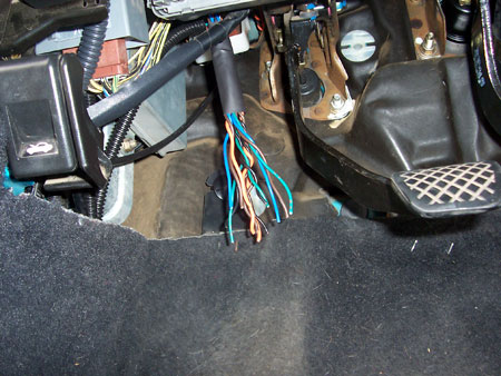
Brake Switch
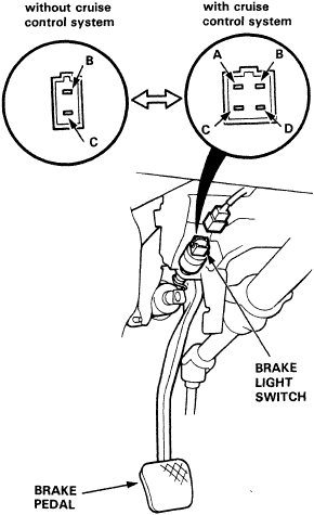
It's easiest to re-pin your brake harness to the four pin harness before the pedal assembly is mounted. B and C in the above diagram goes to B and C on the four pin harness. There are two light green wires on one pin on the four pin harness. One branch goes to the module, the other goes to the Main Switch. Gray goes to the gray on the module. Branch off the grn/wh wire and run it to the grn/wh on the module.
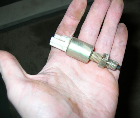
Clutch Switch
The pink wire on the Auto Cruise Module goes to the pi/blk wire on the lower clutch switch.
Under-Dash Fuse Box
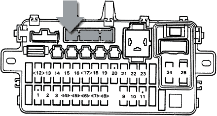
The blk/yel's from the Auto Cruise Module and the Cruise switch can be joined to the blk/yel wire in the top left of the gray plug on the under-dash fuse box.
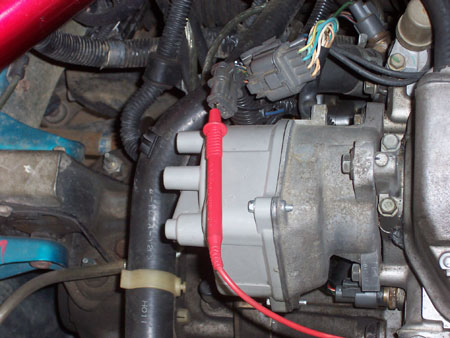
Cruise Actuator
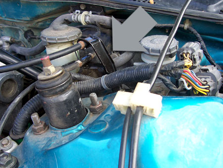
The Cruise Control Actuator has four wires. One goes to chassis ground via a ring terminal. The other three run into the passenger compartment and are wired color for color to the Auto Cruise Module.
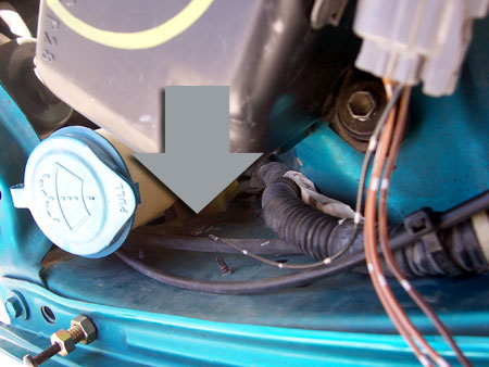
Crimp a ring terminal onto the black wire and ground it at the 10mm bolt shown here.


Resume/Accel Set/Decel Switch
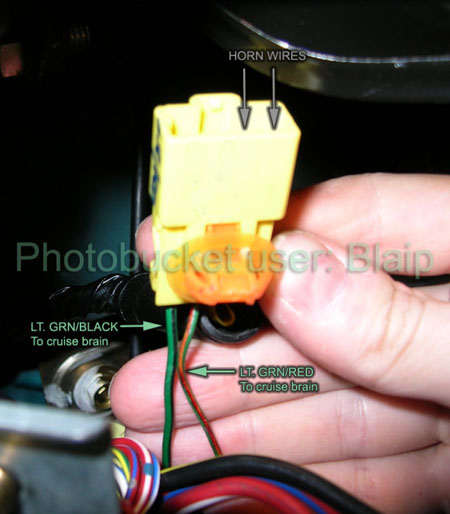
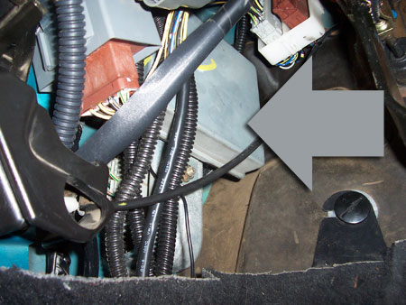
De-pin the lt grn/blk and lt grn/red wires from the yellow connector that came from the steering column on the donor car, wire them to your Auto Cruise Module, and pin them into the empty slots on your car's connector. DO NOT mess with the other two wires. One is for the horn and the other triggers the airbag.
Auto Cruise Module
| Wire Color | Connects To | |
|---|---|---|
| Brn/Wh | Cruise Actuator | Brn/Wh |
| Gray | Brake Switch | Gray |
| Black | Ground | Chassis |
| Grn/Wh | Brake Switch | Grn/Wh |
| Lt Grn/Red | Set/Decel Button | Lt Grn/Red |
| Lt Grn/Blk | Resume/Accel Button | Lt Grn/Blk |
| Blue | Tach Behind Cluster | Blue |
| Brown | Cruise Actuator | Brown |
| Red/Blu | Cruise Indicator Light Behind Cluster | Red/Blue |
| Brn/Blk | Cruise Actuator | Brn/Blk |
| Blk/Yel | Fuse Box | Blk/Yel |
| Yel/Blu | VSS Behind Cluster | Yel/Blu |
| Lt Grn | Cruise Switch AND Brake Switch | Lt Grn |
| Pink | Lower Clutch Switch | Pi/Blk |
Cruise Switch
| Wire Color | Connects To | |
|---|---|---|
| Blk/Yel | Fuse Box | Blk/Yel |
| Lt Grn | Auto Cruise Module | Lt Grn |
| Black | Dimmer Switch | Black |
| Red/Blk | Dimmer Switch | Red/Blk |
| Red | Dimmer Switch | Red |
Cruise Indicator Light (optional)
| Wire Color | Connects To | |
|---|---|---|
| Yellow | Fuse Box | Blk/Yel |
| Empty | ||
| Black | Dimmer & Cruise Switch | Black |
| Red/Blk | Dimmer & Cruise Switch | Red/Blk |
| Red/Blu | Auto Cruise Module | Red/Blu |
Cruise Actuator
| Wire Color | Connects To | |
|---|---|---|
| Black | Ground | Chassis |
| Brn/Blk | Auto Cruise Module | Brn/Blk |
| Brown | Auto Cruise Module | Brown |
| Brn/Wh | Auto Cruise Module | Brn/Wh |
Finishing Up
Testing Auto Cruise Module Harness
Continuity to Ground
To test for continuity to ground, set the meter to continuity. Put the black probe of your multimeter in the door pin or the key cylinder to ground it, and the red probe to the circuit you're testing. Most meters will make a tone.
Battery Voltage
Set the meter to 20V DC. Put the red probe on the wire and ground the black probe. The meter should show about 12V. The same reading as if you put the red meter directly to the battery's positive post and the black meter to the negative.
Ground a Wire
Take a piece of spare wire, strip each end. Ground one side to the chassis and put the other end on the wire. Never put ground to any wire with a yellow harness plug or in yellow split loom. These are the SRS wires, and if you ground one, it could deploy the airbag and kill you.
Put Power to a Wire
Never put power straight to a wire w/out a fuse. Get an inline fuse holder, strip each end, and insert a low amp fuse. 7.5A are pretty easy to find. The far left option output on the under-dash fuse box is a convenient constant 12V.
- Black continuity to ground.
- Blk/yel battery voltage when key is in 2nd position.
- Lt grn battery voltage when key is in 2nd position, main switch on.
- Gray key in 2nd position, main switch on, press brake pedal, 0 volts. Release brake pedal, battery voltage.
- Grn/wh push brake pedal, battery voltage. Release brake pedal, 0 volts.
- Red/blu ignition in 2nd position, ground this wire and the Cruise Indicator Light should come on.
- Lt grn/blk hold Resume button, battery voltage.
- Lt grn/red hold Set button, battery voltage.
- Pink clutch pedal released or auto tranny in Park or Neutral no continuity to ground. Clutch pedal pressed or auto tranny in any other setting, continuity to ground.
- Blue battery voltage when engine is running.
- Orange key in 2nd position, main switch on, front wheels off the ground, wheel rotated by hand, voltage should cycle between 0-10 volts when the wheel is rotating.
- Brn/wh and Brn/blk connect power to brn/wh and ground brn/blk you should hear the Cruise Actuator motor running.
- Brn/red connect to power and you should hear the Actuator motor lock the cable in place.
Helms Manual Errors
The Helms Manual has several errors in the wiring diagrams and written information. It's not exclusive to the cruise control info- I find them all the time. I'll list what I noticed in case anyone is using the Helms to troubleshoot.
- A, B, C, D labeled incorrectly on the brake switch in the wiring diagram
- Speed Sensor alternates 0-12V not 0-5V as stated.
- The Clutch Switch is normally open, not normally closed.