

- Mon Jun 11, 2007 2:59 pm
#10569
This is a pretty simple procedure. If you have any experience in soldering, the right tools, and a steady hand, you could do this yourself.
The Tools:
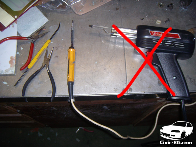
You'll need a small soldering iron and some very small needle nose pliers.
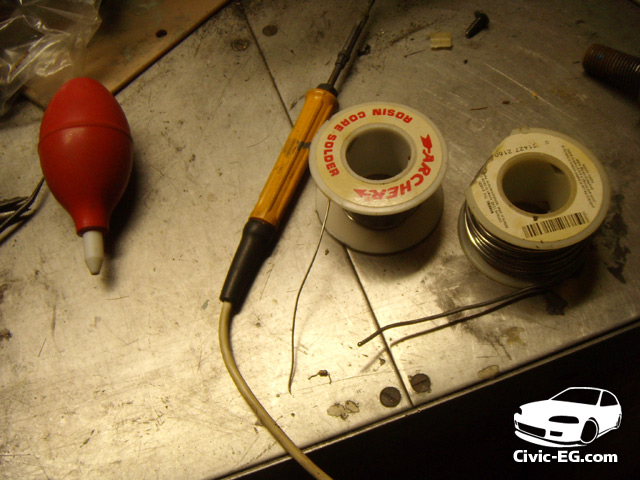
Use thin solder like on the left.
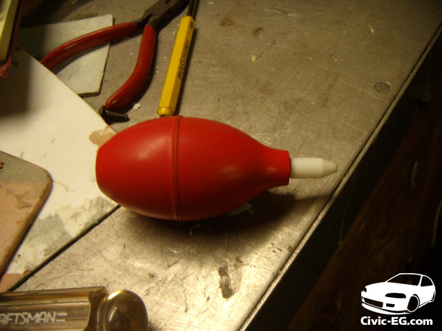
This is a vacuum to remove old solder. Pick it up, squeeze it, and hold it on the back of the board where you need to remove old solder from a hole. Then heat the solder in the hole from the other side of the board. When the solder heats up and turns into liquid, take your hand pressure off the vacuum and suck the melted solder in the ball.
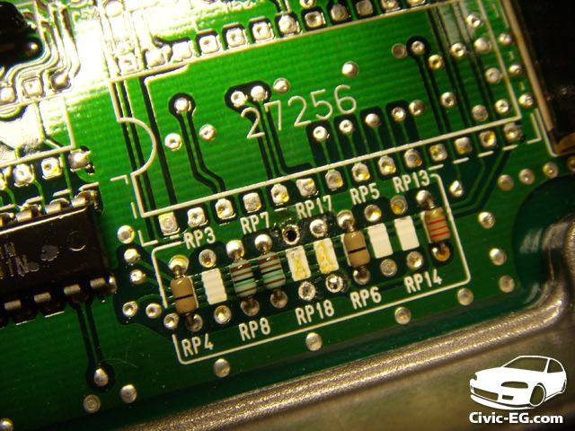
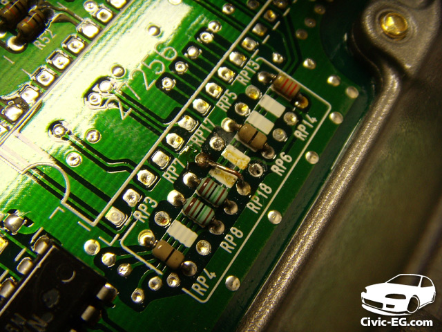
Here is an Auto P28:
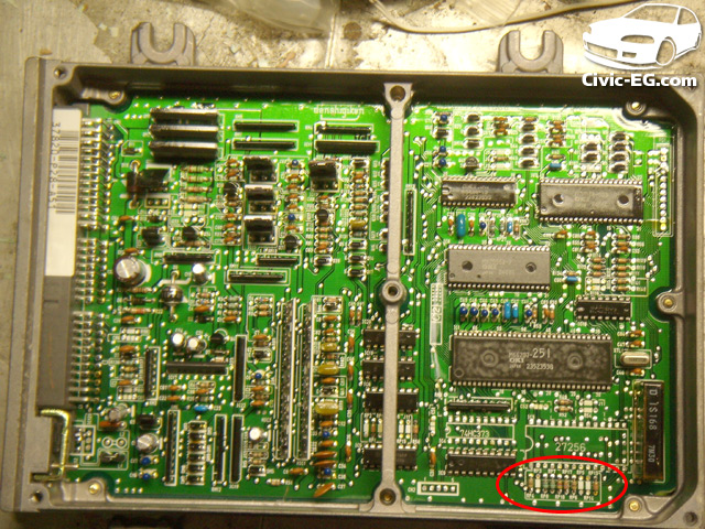
you only need to be concerned with the area in the red circle, everything else stays the same.
You can see the code on the top left... the second to last number is a 5.
check this thread for a quick reference to tell if your ECU is auto or manual: http://civic-eg.com/viewtopic.php?p=10568
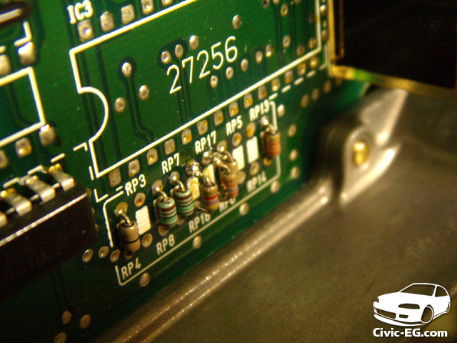
To convert the ECU to manual, you'll be removing the resistors from RP17 and RP18. Then Replacing the RP18 resistor with a jumper.
Above, the Resistors have already been started on...
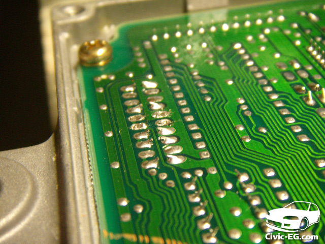
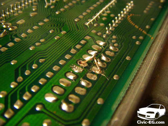
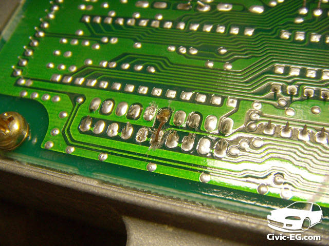
Here's the back side of the board. You can see the 2 empty spaces where I have already pulled the RP17 and RP18 resistors through. Notice the remaining resistors... The wire that goes through is bent down like a tab & soldered to the board. To remove the resistor, you first need to heat up that solder and bend the wire straight up so that you can pull it through the board.
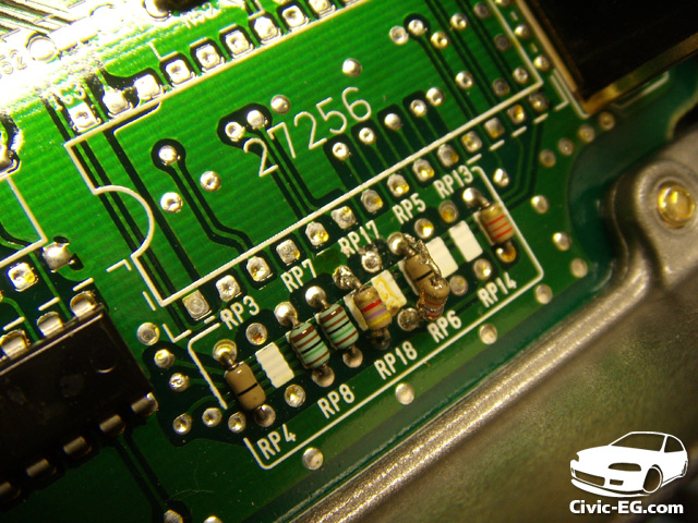
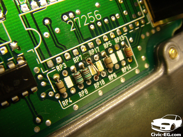
Now back to the top of the board, I have pulled one side of the RP17 resistor completely through. After you bend the tabs on the bottom, heat the terminal from the top and the resistor will pull right out when the solder becomes liquid.
Here the resistor has been completely removed. Just repeat the process for the other resistor now.
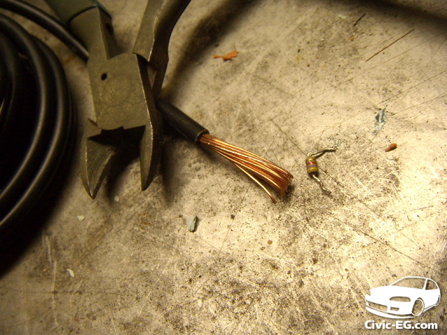
The resistor in RP18 needs to be replaced with a jumper. A jumper = a solid wire. To do this, I took one strand of wire from a copper wire. This wire was not the kind with the real fine strands like some expensive speaker wire, but just your average 14 ga power wire.
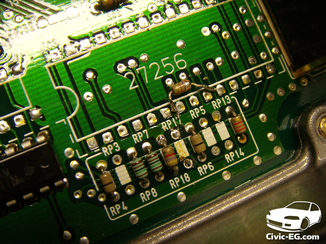
In the pic above, You can see I cleaned out the top hole of RP18 using the vacuum. You'll be installing the jumper in RP18, so the holes need to be open. RP17 doesn't matter if the holes are clean or filled with the old solder.
take your single strand of wire and bend it in a U shape, then put it through from the top side of the board.
On the bottom of the board, bend the wire to make tabs. Mine are a little long... I trimmed them down to the same size as the others after the pics.
Here I soldered the jumper from the top side of the board.
The soldering iron wasn't very clean and the first solder I made on the top of RP18 is a little dirty. I used the vacuum to remove it and do it again.
Clean your iron first!
Here's another pic of the back of the board, before I finished trimming down those tabs.
This whole operation takes less than 30 mins.
Now you won't get a CEL 19 when using an auto P28 in a manual car!
The Tools:
You'll need a small soldering iron and some very small needle nose pliers.
Use thin solder like on the left.
This is a vacuum to remove old solder. Pick it up, squeeze it, and hold it on the back of the board where you need to remove old solder from a hole. Then heat the solder in the hole from the other side of the board. When the solder heats up and turns into liquid, take your hand pressure off the vacuum and suck the melted solder in the ball.
Here is an Auto P28:
you only need to be concerned with the area in the red circle, everything else stays the same.
You can see the code on the top left... the second to last number is a 5.
check this thread for a quick reference to tell if your ECU is auto or manual: http://civic-eg.com/viewtopic.php?p=10568
To convert the ECU to manual, you'll be removing the resistors from RP17 and RP18. Then Replacing the RP18 resistor with a jumper.
Above, the Resistors have already been started on...
Here's the back side of the board. You can see the 2 empty spaces where I have already pulled the RP17 and RP18 resistors through. Notice the remaining resistors... The wire that goes through is bent down like a tab & soldered to the board. To remove the resistor, you first need to heat up that solder and bend the wire straight up so that you can pull it through the board.
Now back to the top of the board, I have pulled one side of the RP17 resistor completely through. After you bend the tabs on the bottom, heat the terminal from the top and the resistor will pull right out when the solder becomes liquid.
Here the resistor has been completely removed. Just repeat the process for the other resistor now.
The resistor in RP18 needs to be replaced with a jumper. A jumper = a solid wire. To do this, I took one strand of wire from a copper wire. This wire was not the kind with the real fine strands like some expensive speaker wire, but just your average 14 ga power wire.
In the pic above, You can see I cleaned out the top hole of RP18 using the vacuum. You'll be installing the jumper in RP18, so the holes need to be open. RP17 doesn't matter if the holes are clean or filled with the old solder.
take your single strand of wire and bend it in a U shape, then put it through from the top side of the board.
On the bottom of the board, bend the wire to make tabs. Mine are a little long... I trimmed them down to the same size as the others after the pics.
Here I soldered the jumper from the top side of the board.
The soldering iron wasn't very clean and the first solder I made on the top of RP18 is a little dirty. I used the vacuum to remove it and do it again.
Clean your iron first!
Here's another pic of the back of the board, before I finished trimming down those tabs.
This whole operation takes less than 30 mins.
Now you won't get a CEL 19 when using an auto P28 in a manual car!
Last edited by teal_dx on Thu Aug 21, 2014 4:12 pm, edited 1 time in total.
Do Not PM me your technical questions. Post them in the forum! 
My 1992 SOHC Turbo Hatch
My Youtube Channel: 6th Gear Garage
My 1992 SOHC Turbo Hatch
My Youtube Channel: 6th Gear Garage


 hail brian


