ECU, Wiring, Sensors
By ballistic
#120087 Ok, so I'm setting up my greddy blue box and I need to solder 2 wires to the map sensor wire going to the ECU, but in the place where it says this wire should be, there is no wire, here is the diagram I am looking at, maybe someone could shed some light as to what wire it is supposed to go to? :?

http://s87.photobucket.com/albums/k135/ ... iagram.png

The 2 wires I am talking about are the green and white wires at the bottom.


Thanks
User avatar
By 3kkl3sia
#120088 Image
By ballistic
#120164 anyone know? I really gotta get this running correctly asap
By ballistic
#120211
suspendedHatch wrote:Which wire is missing?


The wire that they say I am supposed to connect the green and white wire to it's the 3rd wire in on the 22pin connector on the top, they say that is the MAP sensor wire, I was wondering if maybe there is a different wire that is the MAP sensor wire, or if theres another way to wire this.


Thanks
By ballistic
#120245
teal_dx wrote:also would be helpful to know your year car, engine, ecu...


94 Civic EX

d16z6

p28


someone help :shock:
User avatar
By teal_dx
#120275 so bone stock, that will make things easier at least...
and you're sure the directions are for your car?
Do you see the 2 wires they are pointing out anywhere else on that harness?
Do you have a helms or chiltons manual? I would compare with their wiring diagrams..
By ballistic
#120283
teal_dx wrote:so bone stock, that will make things easier at least...
and you're sure the directions are for your car?
Do you see the 2 wires they are pointing out anywhere else on that harness?
Do you have a helms or chiltons manual? I would compare with their wiring diagrams..


Yes, the directions are for the 92-95 civic EX's and everything else matches up perfectly to this point.

and no I do not have a helms/chilton manual, maybe someone could upload a pic or something of a diagram for this, that would be fantastic :)
By ballistic
#120316 
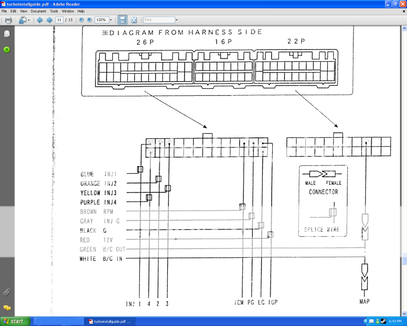
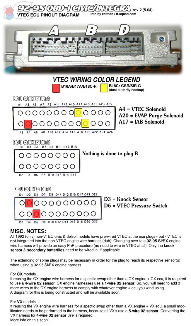
ok, so I'm looking at this list of wires and codes, and I'm trying to decipher whether this wire they claim is the MAP sensor wire is a wire that I have on my ECU harness. here is the list.

A1 BRN INJ1 INJ1
A2 YEL INJ4 INJ4
A3 RED INJ2 INJ2
A4 ORN/WHT VTS VTEC solenoid
A5 LT BLU INJ3 INJ3
A6 ORN/BLK PO2SHTC O2 sensor (heating element)
A7 GRN/YEL FLR1 fuel pump
A8 (empty)
A9 GRN/WHT IACV IAC valve
A10 (empty)
A11 (empty)
A12 YEL/GRN FANC Fan Output
A13 GRN/ORN MIL MIL (check engine light)
A14 (empty)
A15 BLK/RED ACC (a/c compressor clutch)
A16 WHT/YEL ALT C alternator
A17
A18 (empty)
A19 (a/t trans only)
A20 RED PCS EVAP purge control solenoid
A21 RED/GRN ICM ICM
A22 (empty)
A23 BLK PG1 ground
A24 BLK PG2 ground
A25 YEL/BLK IGP2 to main relay and to gound for o
A26 BRN/BLK LG1 gound
B1 YEL/BLK IGP2 to pin A25
B2 BRN/BLK LG2 ground to shields for CYP & TDC
B3 (a/t trans only)
B4 (a/t trans only)
B5 BLU/RED ACS a/c switch
B6 (empty)
B7 (a/t trans only)
B8 BRN/RED PSPSW PSP switch
B9 BLU/WHT clutch interlock switch
B10 YEL/BLU VSS vehicle speed sensor
B11 ORN CYP P CYP -P
B12 WHT CYP M CYP -M
B13 ORN/BLU TDC P TDC -P
B14 WHT/BLU TDC M TDC -M
B15 BLU/GRN CKP P CKP -P
B16 BLU/YEL CKP M CKP -M
D1 WHT/BLU VBU Back Up Power
D2 GRN/WHT BKSW brake switch
D3 KS Knock Sensor
D4 BRN SCS service check connector
D5 (empty)
D6 ORN/BLU VTM VTEC pressure switch
D7 LT BLU TXD/RXD (data link connector)
D8 (empty)
D9 PNK ALT F alternator
D10 GRN/RED ELD electric load detector
D11 RED/BLU TPS TPS Signal
D12 YEL/GRN
D13 RED/WHT ECT ECT sensor
D14 WHT PHO2S O2 sensor
D15 RED/YEL IAT IAT sensor
D16 WHT/YEL VREF VREF
D17 WHT MAP Map Signal

D18 (a/t trans only)
D19 YEL/GRN VCC1 MAP 5V
D20 YEL/WHT VCC2 TPS 5V
D21 GRN/BLU SG1 MAP GND
D22 GRN/WHT SG2 TPS GND


The bolded one (D17 WHT MAP Map Signal) is the one I am talking about, could anyone put in english which wire this is on the actual harness?


Thanks, and sorry for acting like an idiot, I been so tired and I'm just trying to get this done with the least trouble possible.


EDIT:

I found this diagram
http://ff-squad.com/tech/wiring/wiring.92-95.jpg

and it says that D17 is the third one over on the top of the 22 pin clip, just like the Blue Box install manual says, but on my ECU clip I dont have a wire that goes to that part, will I have to get a clip thing and attach it to the ECU manually like that? or is there another way to do this?
Last edited by ballistic on Wed Jun 03, 2009 3:07 am, edited 1 time in total.
User avatar
By Sentry
#120317 The blue box has two wires for the MAP sensor since it alters the signal. MAP in and MAP out. This is basically what the diagram is trying to show, they just aren't very clear.

Image
User avatar
By Sentry
#120318
ballistic wrote:The bolded one (D17 WHT MAP Map Signal) is the one I am talking about, could anyone put in english which wire this is on the actual harness?

It's the white wire on the second-biggest connector.
By ballistic
#120320
Sentry wrote:
ballistic wrote:The bolded one (D17 WHT MAP Map Signal) is the one I am talking about, could anyone put in english which wire this is on the actual harness?

It's the white wire on the second-biggest connector.


could this white wire be in a different location than the one that they state it should be in??

Thanks for the help
User avatar
By Sentry
#120321 Nope, it's the only white wire on the ECU harness. Just have a look at the pinout diagram GReddy gave and make sure the wire doesn't have any other colour stripes on it.